Vehicle seat slide device

A technology for sliding devices and vehicles, which is applied in the direction of vehicle seats, special positions of vehicles, movable seats, etc. It can solve problems such as dimensional tolerances and assembly errors, and achieve the effects of reducing sliding resistance, suppressing abnormal noise, and improving assembly.

Inactive Publication Date: 2010-05-12
AISIN SEIKI KK
View PDF1 Cites 9 Cited by
  • Summary
  • Abstract
  • Description
  • Claims
  • Application Information

AI Technical Summary

Problems solved by technology

However, due to dimensional tolerances in the manufacture of the cage, lower rail, upper rail, etc., assembly errors when assembling the two rails, etc., the cage may come into contact with one or both rails.
Generally, the cage is made of metal such as iron, so when the upper rail slides relative to the lower rail while the cage is in contact with the rail, abnormal noise may occur.

Method used


Image

  • Vehicle seat slide device
  • Vehicle seat slide device
  • Vehicle seat slide device

Examples


Embodiment Construction

[0024] Next, a vehicle seat sliding device according to an embodiment of the present invention will be described with reference to the drawings.

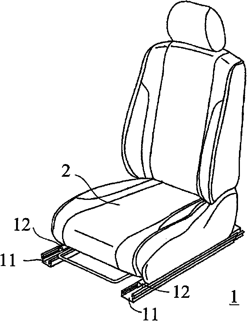
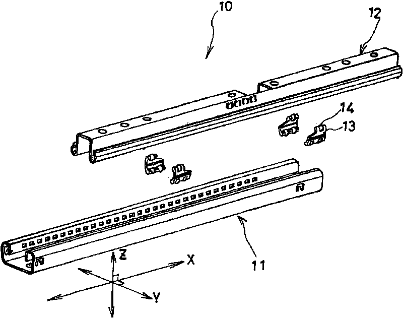
[0025] Such as figure 1 , figure 2 , image 3 As shown, the seat sliding device 10 includes a pair of left and right lower side rails 11 fixed on the upper surface of the vehicle floor 1 and fixed on the lower surface of the vehicle seat 2 and respectively slidable relative to each lower side rail 11. A pair of left and right upper side rails 12 installed. The upper side track 12 can freely move towards the figure 2 The front-back direction X of the vehicle is shown moving by a predetermined amount.

[0026] Next, a detailed structure of the seat slide device 10 will be described.

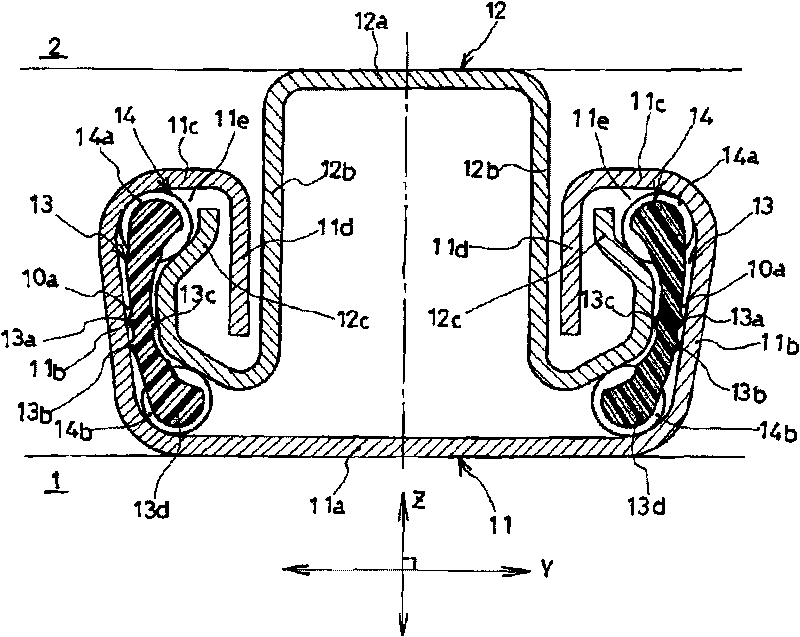
[0027] The lower rail 11 is formed by bending a sheet material. The lower rail 11 is extended long in the front-rear direction X of the vehicle, such as image 3 As shown, there is a planar bottom 11a and a pair of left and right upright walls 11...


PUM


Abstract

Noise occurring when an upper rail is slid on a lower rail with retainers in contact with either or both of the rails is suppressed. A vehicle seat slide device (10) has the lower rail (11), the upper rail (12), the retainers (13) disposed between both rails (11, 12), and rolling elements (steel balls) rollably supported by the retainers (13) and rolling while being in contact with both rails (11, 12). Each retainer (13) has a retainer body (13d) and projections (13a, 13b, 13c) projecting from the retainer body (13d). The projections (13a, 13b, 13c) are formed of a resin material integrally with the retainer body (13d). Because of the projections (13a, 13b, 13c) formed on the retainer (13), when the retainers (13) make contact with both rails (11, 12), the projections (13a, 13b, 13c) invariably make contact with both rails (11, 12).

Description

technical field [0001] The present invention relates to a seat sliding device for a vehicle. Background technique [0002] Conventionally, a device disclosed in JP-A-2005-263049 is known as such a vehicle seat sliding device. [0003] The vehicle seat sliding device is composed of a lower rail fixed on the vehicle floor and an upper rail supporting the seat so as to be slidable, and the seat can be moved by the relative movement of the two rails based on the sliding. Swipe to move. The lower rail has a pair of lower flange portions formed in a substantially U-shape, and the upper ends of the respective standing wall portions protrude inwardly and fold back downward. In addition, the upper rail has a pair of upper flange portions formed in a substantially inverted U-shape, and the lower ends of the respective standing wall portions protrude outward while being folded upward. The lower rail and the upper rail form a substantially box-shaped seat slide device by assembling t...

Claims


Application Information

Patent Timeline
Patent Type & Authority Applications(China)
IPC IPC(8): B60N2/06
CPCB60N2205/20B60N2/0722B60N2/0715B60N2/0705F16C29/04F16C33/416F16C33/40
Inventor 小岛康敬二本松英雄
Owner AISIN SEIKI KK
Why Eureka
Try Eureka