Optical fiber point diffraction phase shifting interferometry of optical plane surface shape

A point-diffraction phase-shifting and interferometric measurement technology, applied in the field of optical measurement, can solve the problems of flatness error, three-plate and other absolute measurement methods cannot achieve full-scale measurement, and the accuracy of flat-surface measurement is limited, so as to expand the application range. Effect

Inactive Publication Date: 2010-05-19
BEIJING INSTITUTE OF TECHNOLOGYGY
View PDF0 Cites 11 Cited by
  • Summary
  • Abstract
  • Description
  • Claims
  • Application Information

AI Technical Summary

Problems solved by technology

[0007] The purpose of the present invention is to solve the problem that there is a flatness error in the reference plane of an ordinary interferometer, which leads to the limited accuracy of its plane shape measurement and th

Method used


Image

  • Optical fiber point diffraction phase shifting interferometry of optical plane surface shape
  • Optical fiber point diffraction phase shifting interferometry of optical plane surface shape
  • Optical fiber point diffraction phase shifting interferometry of optical plane surface shape

Examples


Embodiment Construction

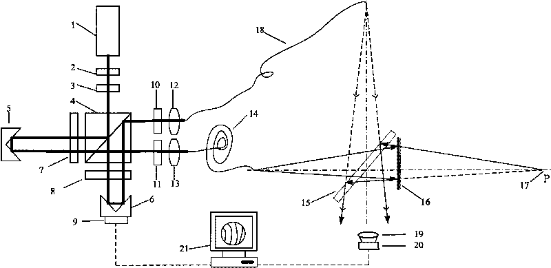
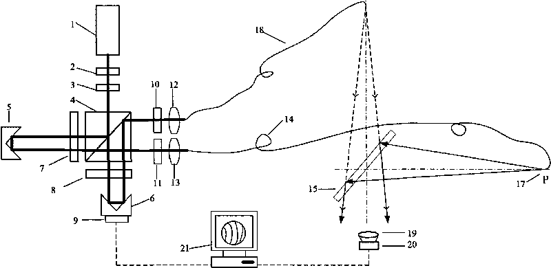
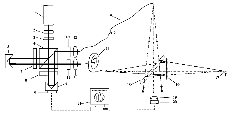
[0023] A kind of optical plane shape optical fiber point diffraction phase-shifting interferometry method of the present invention, the measuring device that realizes this method, such as figure 1 , figure 2 As shown, it includes a spectroscopic system, a measuring fiber 14, a reference fiber 18, a beam splitter 15, an imaging lens 19, a CCD camera 20, a computer 21, and a measured plane mirror 16; the spectroscopic system includes a laser 1, an adjustable neutral density filter 2. 1 / 2 wave plate 3, polarizing beam splitter 4, rectangular prism A5, rectangular prism B6, 1 / 4 wave plate A7, 1 / 4 wave plate B8, piezoelectric ceramic 9, polarizing plate A10, polarizing plate B11, Microscopic objective lens A12 and microscopic objective lens B13; Its concrete implementation steps are:

[0024] The first step: if figure 1 Shown: the linearly polarized light emitted from the laser 1 is attenuated by the adjustable neutral density filter 2, the polarization direction is adjusted by ...


PUM


Abstract

The invention relates to an optical fiber point diffraction phase shifting interferometry of an optical plane surface shape, belonging to the field of optical measuring technique. The interferometry of the invention comprises the following steps: penetrating a beam splitter from a spheric wave for measuring the optical fiber diffraction, and refracting after reflecting on the surface of the plane mirror to be measured; reflecting the spheric wave front by the beam splitter, diffracting with the reference optical fiber, and converging with the spheric wave front of the beam splitter to generate interference; analyzing and processing the interference figure by using a standard method; measuring to obtain the surface shape of the measured plane mirror and the aberration introduced by the beam splitter; removing the plane mirror to be measured, moving the measuring optical fiber to the end surface of the reference optical fiber in the conjugate position relative to the beam splitter, and converging the spheric wave front diffracted from the reference optical fiber and the spheric wave front diffracted from the measuring optical fiber to generate interference again; measuring to obtain the aberration introduced by the beam splitter; and subtracting the measuring result obtained in step 2 from the measuring result obtained in step 1 to obtain the surface shape of the measured plane mirror. The interferometry of the invention has high precision of the measuring result of the plane surface shape, is an absolute measurement method of the plane surface shape, and extends the application range of the point diffraction interferometry.

Description

technical field [0001] The invention relates to an optical plane shape optical fiber point diffraction phase-shifting interferometry method, which belongs to the technical field of optical measurement. Background technique [0002] Planar optical elements are widely used in optical systems, and their functions are mainly to deflect light paths and form images, and their flatness is usually below one wavelength. The surface shape measurement of the optical plane generally adopts the interference method, which requires a standard reference plane as the plane datum. A common interferometer uses a standard flat plate manufactured by optical processing as a reference plane, and there is always a certain surface shape, which limits the accuracy of the interferometer’s measurement of the plane shape. The current measurement accuracy of the interferometer’s plane shape can only be Reach λ / 20~λ / 50 (wavelength is 632.8nm). It is far from meeting the needs of cutting-edge technology ...

Claims


Application Information

Patent Timeline
IPC IPC(8): G01B11/24G01B9/023
Inventor 陈凌峰任雅青吴朔李杰沙定国
Owner BEIJING INSTITUTE OF TECHNOLOGYGY
Why Eureka
Try Eureka