
Antenna having distributed phase shift mechanism

An antenna and antenna assembly technology, applied in the field of signal phase shift, can solve problems such as increasing workload

Inactive Publication Date: 2010-05-19
PCTEL INC
View PDF2 Cites 1 Cited by
  • Summary
  • Abstract
  • Description
  • Claims
  • Application Information

AI Technical Summary

Problems solved by technology

Although these processes are effective, they also increase the workload

Method used


Image

  • Antenna having distributed phase shift mechanism
  • Antenna having distributed phase shift mechanism
  • Antenna having distributed phase shift mechanism

Examples


Embodiment Construction

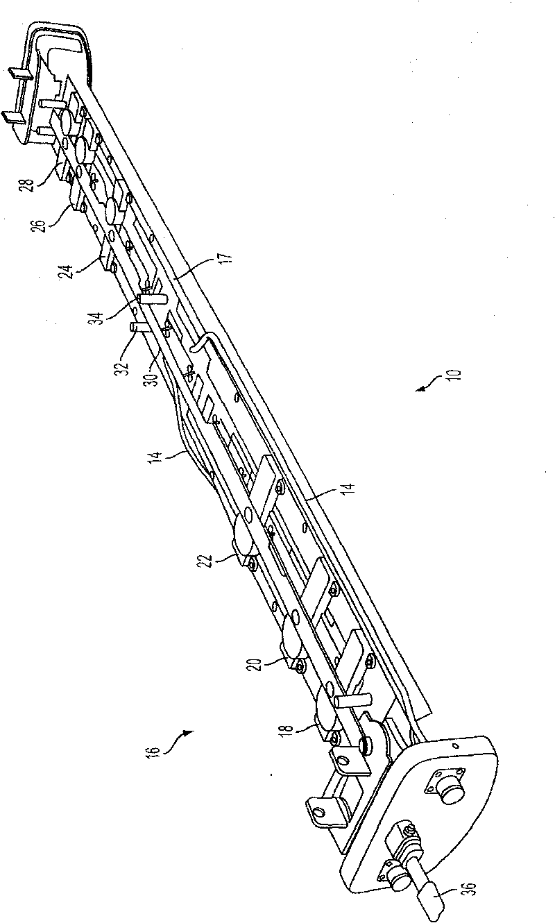
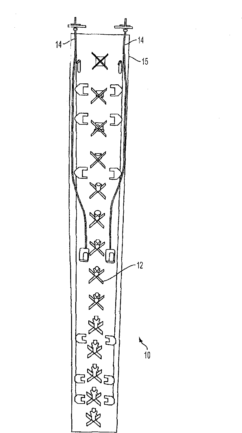
[0025] figure 1 It is a perspective side view of an antenna 10 with an adjustable downtilt generally shown according to an exemplary embodiment of the present invention. figure 2 Is to remove the protective cover figure 1 Front view of the antenna 10. Such as figure 2 As shown, the antenna 10 is approximately 48 inches in length and has 14 antenna components 12 that together form an antenna array on the ground plane 15. The antenna array 10 may be coupled to the transceiver through the conductor 14. The antenna 10 and the transceiver may operate to modulate the radio frequency signal modulated by the information signal at a suitable transmission frequency (for example, 3.3-3.8MHz) between the base station and one or more wireless devices of a suitable category (for example, iPhone, personal computer, etc.) Make coupling.

[0026] The downward tilt of the antenna 10 can be controlled by an actuator system (for example, a rack and pinion system) 16 coupled to a plurality of phas...


PUM


Abstract

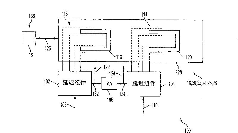
An antenna is provided. The antenna includes a first antenna element disposed over a ground plane and a second and third antenna element over the ground plane on opposing sides of the first antenna element, said first, second and third antenna elements forming a linear antenna array. The antenna further includes an electrical delay line having first and second conductors extending between the first and second antenna elements and between the first and third antenna elements, a parallel conductive elements disposed in series with each of the first and second conductors, the conductive elements extending away from the first and second conductors in a single direction perpendicular to a predominant axis of the linear array, a tuning substrate extending across the conductive elements of each of the delay lines with a pair of U-shaped conductive elements on opposing ends of the tuning substrate with opposing arms of each of the U-shaped tuning elements capacitively engaging respective, corresponding portions of the tuning stubs of the first and second conductors in a substantially identical manner and an actuator system that advances the tuning substrates transverse to the predominant axis thereby increasing an electrical delay on the second antenna and decreasing the electrical delay of the third antenna by substantially equal values.

Description

[0001] Cross references to related applications [0002] This application is a partial continuation application of U.S. Provisional Patent Application No. 61 / 092,229 filed on August 27, 2008, and the content is incorporated herein by reference. Technical field [0003] The field of the invention relates to antenna arrays, and in particular to signal phase shifts with such arrays. Background technique [0004] Antenna arrays used in wireless communication systems are well known. Such an array can be used in any number of different types of systems (e.g., cellular communication network, WiFi, etc.). [0005] One of the important features of known wireless systems is the ability to provide seamless coverage. For example, a user of a cellular phone on a car trip may find it annoying to frequently lose call connections (eg, call dropped) during use. This problem was once common, but it has become less serious due to advances in wireless technology. [0006] In order to avoid dropped call...

Claims


Application Information

Patent Timeline
Patent Type & Authority Applications(China)
IPC IPC(8): H01Q3/34
CPCH01Q1/246H01Q3/32
Inventor 凯文·T·勒藩斯高·X·高麦之
Owner PCTEL INC
Learn More