Extrusion molded article
A technology of extrusion molding and extrusion direction, which is applied in the direction of catalyst carrier, dispersed particle separation, grinding/polishing equipment, etc., can solve the problems of easy cracking and cracking, and achieve the effects of cracking resistance, cracking reduction and strength improvement
- Summary
- Abstract
- Description
- Claims
- Application Information
AI Technical Summary
Problems solved by technology
Method used
Image
Examples
Embodiment 1
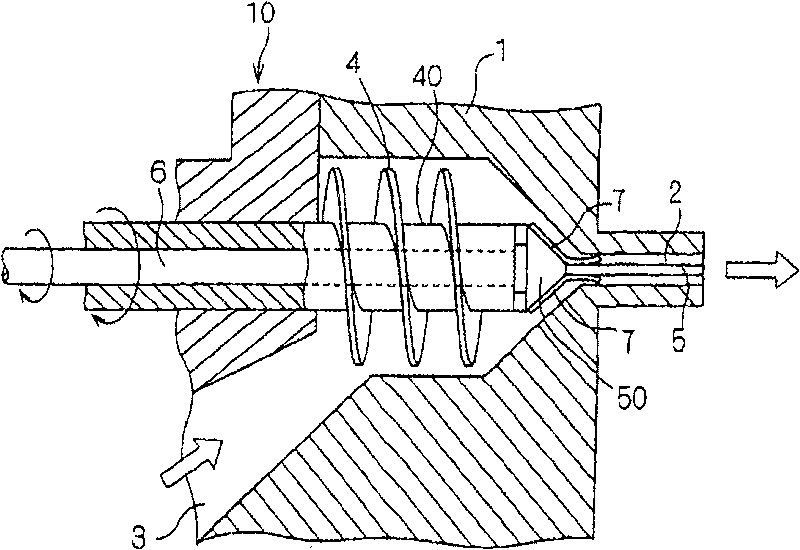
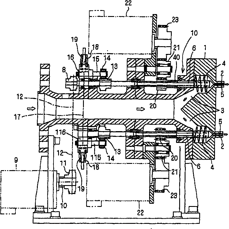
[0054] use figure 1 , figure 2 The extrusion molding apparatus shown extrudes a clay-like alumina catalyst molding material to manufacture its molded product. The alumina molding material contained 6 parts by weight of alumina fibers having an average fiber length of 0.4 mm and 38 parts by weight of water relative to 100 parts by weight of the catalyst.
[0055] The used die 1 has a chrome-plated surface and has a disc shape in which eight extrusion holes 2 are concentrically arranged. The inner diameter of the extrusion hole 2 is 6.6 mm, and the length is 10 mm.
[0056] A pin 5 with an inner diameter of 2.5 mm and a length of 22 mm is inserted into the extrusion hole 2 . like figure 1 As shown, the rear ends of the three metal wires are fixed on the pin 5, wound on the pin 5 obliquely, and the front ends are slightly tilted from the pin 5.
[0057] Using this extrusion molding apparatus, the above-mentioned alumina catalyst molding material was extrusion-molded at an e...
Embodiment 2
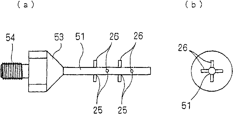
[0059] In addition to using image 3 pin 51 shown in place of the figure 1 Extrusion molding was carried out in the same manner as in Example 1 except for the pin 5 shown. However, the number of wires 26 fitted in the through holes of the pins 51 is two, and the intersection angle of the two wires 26 is 90°.
Embodiment 3
[0061] In addition to using Figure 4 pin 52 shown in place of the figure 1 Extrusion molding was carried out in the same manner as in Example 1 except for the pin 5 shown. However, the number of cross-shaped rings 28 is one.
[0062] [Comparative example]
[0063] Extrusion molding was carried out in the same manner as in Example 1, except that a pin without protrusions was used.
[0064] The strength of the molded articles obtained in the above-mentioned Examples and Comparative Examples was investigated by the following drop test and compressive strength test.
[0065] 〔Compressive strength test〕
[0066] When a pressure is applied along the thickness direction (radial direction) of a molded product with a cutting length of 6.6 mm, the pressure at which the molded product breaks is measured, and this value is taken as the compressive strength.
[0067] 〔Drop strength test〕
[0068] Put the molded product with a cut length of 6.6mm in an environment of 25°C and 80%RH, ...
PUM
| Property | Measurement | Unit |
|---|---|---|
| length | aaaaa | aaaaa |
Abstract
Description
Claims
Application Information
 - R&D
- Intellectual Property
- Life Sciences
- Materials
- Tech Scout
- Unparalleled Data Quality
- Higher Quality Content
- 60% Fewer Hallucinations
Browse by: Latest US Patents, China's latest patents, Technical Efficacy Thesaurus, Application Domain, Technology Topic, Popular Technical Reports.
© 2025 PatSnap. All rights reserved.Legal|Privacy policy|Modern Slavery Act Transparency Statement|Sitemap|About US| Contact US: help@patsnap.com


