Impeller, fan apparatus using the same, and method of manufacturing impeller

A technology of impellers and blades, which is applied to components of pumping devices for elastic fluids, pump devices, non-variable pumps, etc., and can solve problems such as increased noise levels and degradation of static pressure characteristics

Active Publication Date: 2010-05-26
JAPAN SERVO CO LTD
View PDF4 Cites 14 Cited by
  • Summary
  • Abstract
  • Description
  • Claims
  • Application Information

AI Technical Summary

Problems solved by technology

This phenomenon manifests itself most prominently in the fluctuation range, resulting in deteriorati

Method used


Image

  • Impeller, fan apparatus using the same, and method of manufacturing impeller
  • Impeller, fan apparatus using the same, and method of manufacturing impeller
  • Impeller, fan apparatus using the same, and method of manufacturing impeller

Examples


Embodiment Construction

[0031] 1. The first preferred embodiment

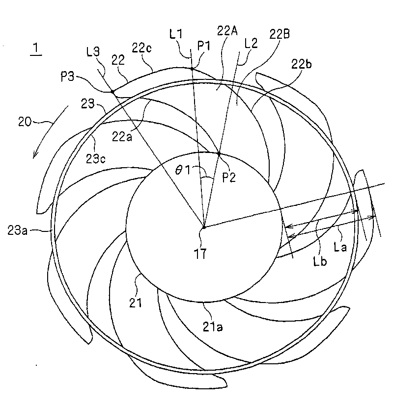
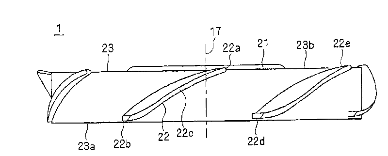
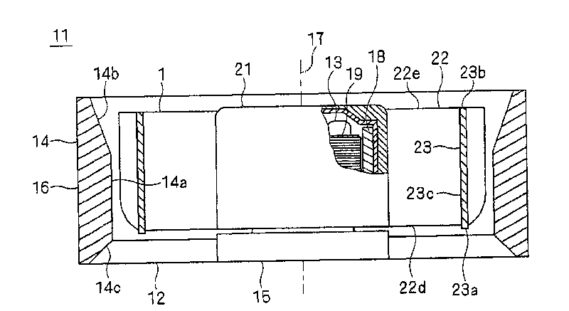
[0032] figure 1 It is a plan view of the impeller 1 according to the first preferred embodiment of the present invention viewed from the inlet side along the central axis 17. figure 2 Is like figure 1 A side view of the impeller 1 shown in. image 3 Is used as figure 1 A cross-sectional view of the fan assembly 11 of the impeller 1 shown in FIG.

[0033] Reference image 3 , The fan device 11 using the impeller 1 according to the preferred embodiment of the present invention includes an impeller 1, a plurality of stationary blades 12, a motor 13, an outer frame member 14 and a support member 15. The stator blades 12, the outer frame member 14 and the support member 15 define the housing 16 of the fan device 11. It is noted in this preferred embodiment that the stationary blade 12 and the supporting member 15 are provided on the outlet side (ie, along the central axis 17 of the impeller 1, for example, image 3 The lower side in the middle...


PUM


Abstract

An impeller, a fan apparatus, and a method of manufacturing the impeller are provided. The impeller includes a support portion, a plurality of rotor blades, and a joining member. The joining member is a substantially annular member provided to strengthen the rotor blades against influence of a centrifugal force, and extends in a circumferential direction along a circle centered on a central axis so as to join the rotor blades to one another. In each of the rotor blades, a point of intersection of a leading edge of the rotor blade with a radially outer end of the rotor blade is positioned forward, with respect to a rotation direction, relative to a point of intersection of the leading edge with an outside surface of the support portion. The joining member is positioned radially inwards of the radially outer end of each of the rotor blades.

Description

Technical field [0001] The present invention relates to an impeller, a fan device using the impeller, and a method of manufacturing the impeller. The impeller has forward-swept blades and is arranged to generate airflow along its central axis around which the impeller rotates. Background technique [0002] Electronic devices such as personal computers or servers are generally provided with cooling fans for cooling electronic components in their housings. As the density of electronic components in the housing increases, the performance of the cooling fan needs to be improved. Generally, cooling fans can be divided into two types: exhaust fans, which are designed to exhaust the hot air in the housing to the outside of the housing; and blowers, which are designed to deliver cooling air directly to the heated Electronic components. In the hair dryer, the direction of the airflow (ie, the direction in which the air is delivered) is important. [0003] In the case of delivering coolin...

Claims


Application Information

Patent Timeline
IPC IPC(8): F04D29/32F04D29/38F04D25/08B29C45/00
Inventor 比护旭日冲哲也旦野太郎伊藤充关口治刘胜伸
Owner JAPAN SERVO CO LTD
Why Eureka
Try Eureka