Electrical kiln with double backward push plates

A dual-channel push plate electric kiln and push plate technology, applied in the field of electric kiln, can solve the problems that the production efficiency of electric kiln cannot be further improved, the heat utilization rate of the firing process is reduced, and it is not well utilized, so as to reduce the burning Reduce manufacturing cost, achieve energy recovery and utilization, and smooth cooling curve

Inactive Publication Date: 2010-05-26
周建华
View PDF0 Cites 5 Cited by
  • Summary
  • Abstract
  • Description
  • Claims
  • Application Information

AI Technical Summary

Problems solved by technology

[0002] Push plate kiln is a commonly used thermal equipment in industry, especially in ceramic industry, building materials industry, refractory industry and other industries, electric kiln is the key equipment in the process of product processing. Push it from the furnace feed port of the electric kiln, pass through the preheating zone, heating zone, high temperature zone, heat preservation zone and cooling zone, and there are heating tubes on both sides of the firing tunnel to heat the products in the kiln. Sometimes, part of the heat will be absorbed by the furnace body, resulting in heat loss and increased energy consumption; the product is cooled by natural cooling, so it will release heat, but this part of the heat has not been well utilized, making the entire combustion The heat utilization rate in the manufacturing process is reduced. In addition, the production efficiency of the electric kiln with a single-channel structure cannot be further improved

Method used


Image

  • Electrical kiln with double backward push plates
  • Electrical kiln with double backward push plates

Examples


Embodiment Construction

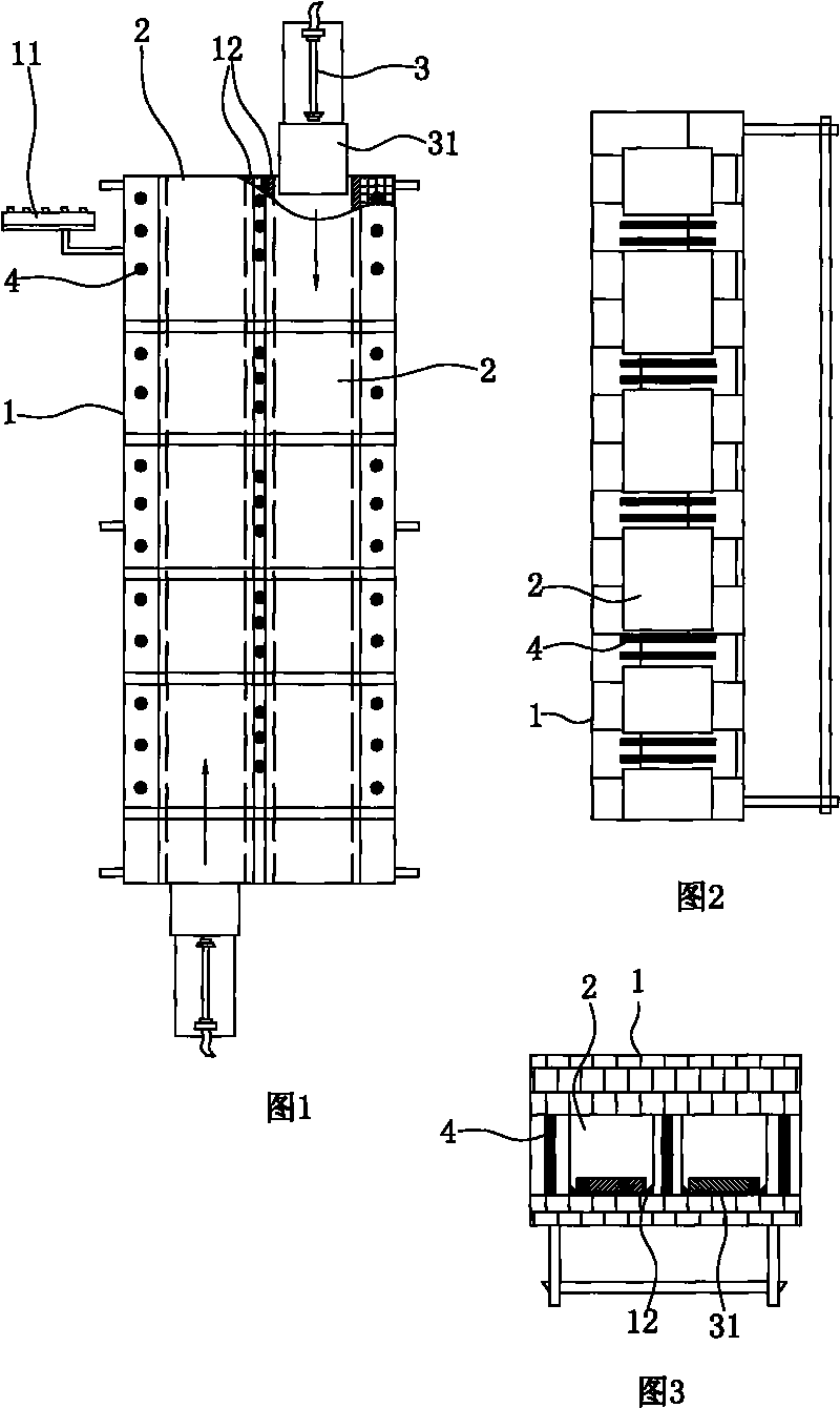
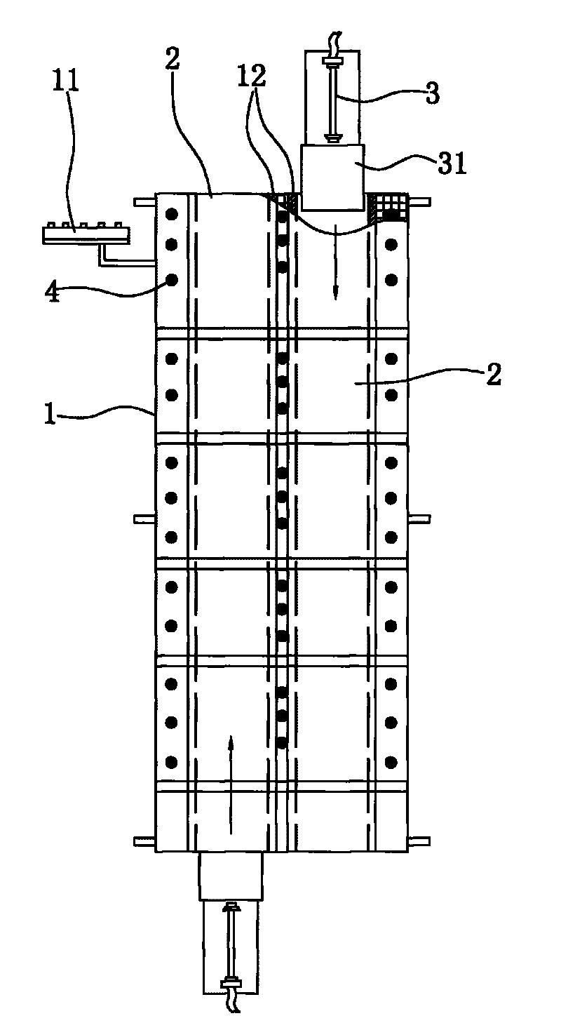
[0015] Such as figure 1 , figure 2 , image 3 As shown, the present invention is a reverse double-channel push plate electric kiln, which includes a furnace body 1, a furnace chamber longitudinally penetrating through the furnace body 1, and heating elements 4 distributed in the two side walls of the furnace chamber. Mechanism, the two propulsion mechanisms are carried out in reverse and synchronously with each other and have their own separate propulsion routes. The furnace can be arranged as two longitudinally running through the firing channels 2, and the two firing channels 2 are connected to each other. into the inlet of channel 2. The propulsion mechanism includes a push plate 31 for placing products. The push plate 31 is installed on the track 12 set in the firing channel 2. A propeller is set at the feeding port of the firing channel 2 to act on the push plate 31 in the track 12. To slide, propeller 3 can adopt hydraulic propeller or mechanical propeller. There i...


PUM


Abstract

The invention discloses an electrical kiln with double backward push plates, comprising a furnace body, a hearth longitudinally penetrated in the furnace body and heating elements distributed in both side walls of the hearth, wherein both ends of the hearth are respectively provided with an advancing mechanism, and two advancing mechanisms mutually have backward synchronous advancements and respectively have an individual advancement line; the hearth consists of two sintering channels longitudinally penetrating the furnace body, and the two sintering channels are communicated at intervals; feed inlets and discharge outlets of the two sintering channels are oppositely arranged; and the advancing mechanisms are arranged at the feed inlets of the two sintering channels. Products in the channels are backwards synchronously moved so as to ensure that partial afterheat of products ignited of the outlet channel is absorbed and utilized by preheated products of the other inlet channel near the outlet channel. The temperature decreasing curve of the electrical kiln is smooth, and the temperature of the products at the outlet of the furnace is low so as to achieve the purposes of recycling energy consumption, reducing the firing cost of the products and improving the firing efficiency of the products.

Description

technical field [0001] The invention relates to an electric kiln, in particular to a push plate electric kiln adopting double-channel reverse synchronous operation. Background technique [0002] Push plate kiln is a commonly used thermal equipment in industry, especially in ceramic industry, building materials industry, refractory industry and other industries, electric kiln is the key equipment in the process of product processing. Push it from the furnace feed port of the electric kiln, through the preheating zone, heating zone, high temperature zone, heat preservation zone and cooling zone, there are heating tubes distributed on both sides of the firing tunnel to heat the products in the kiln. Sometimes, part of the heat will be absorbed by the furnace body, resulting in heat loss and increased energy consumption; the product is cooled by natural cooling, so it will release heat, but this part of the heat has not been well utilized, making the entire combustion The heat ...

Claims


Application Information

Patent Timeline
Patent Type & Authority Applications(China)
IPC IPC(8): F27B9/02F27B9/06F27B9/26F27B9/36F27B9/40
Inventor 周建华
Owner 周建华
Why Eureka
Try Eureka