Induced metamagnetic generating method

A technology that induces current and the direction of magnetic lines of force, applied in the direction of electrical components, can solve problems such as low conversion efficiency, hazards to the power grid, and increased resistance, and achieve the effects of improving power generation efficiency, saving energy, and reducing resistance

Inactive Publication Date: 2010-05-26
徐明 +1
View PDF0 Cites 2 Cited by
  • Summary
  • Abstract
  • Description
  • Claims
  • Application Information

AI Technical Summary

Problems solved by technology

[0002] The traditional generator power generation method has the following deficiencies: First, because the rotor of the traditional generator is the magnetic pole, and the stator is the coil. During the relative circular motion between the two, the magnetic force line and the coil do relative cutting motion, and the induced current of the coil generates The rotating magnetic field of the rotor acts as a hindrance to the rotor. The greater the angle between the position of the coil and the magnetic force line is between 0 and 90 degrees, the greater the resistance of the magnetic force line and the greater the energy consumed
This power generation method only completes the conversion of energy, the conversion efficiency is low, and the energy consumption is large.
Second, magnetic flux leakage easily occurs in the iron core of traditional generators, which increases resistance, wastes power, and generates harmonics, which are harmful to the power grid

Method used


Image

  • Induced metamagnetic generating method
  • Induced metamagnetic generating method
  • Induced metamagnetic generating method

Examples


Embodiment Construction

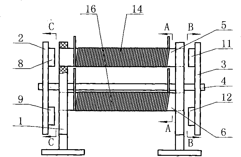
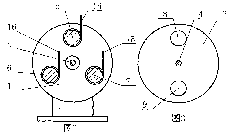
[0009] The induction variable magnetic power generation method described in the present invention uses at least one iron core and at least one magnet group, and a coil is installed on each iron core, and each group of magnets is composed of two magnets, and the two magnets of the same group are opposite to each other. Utilize the relative movement between the iron core and the magnet to change the magnitude of the magnetic flux in the iron core, so that the magnetic flux in the iron core gradually increases from zero to the maximum value, and then gradually decreases from the maximum value to zero. The induced current is generated in the coil, the specific steps are as follows:

[0010] First place the two magnets in each pair of magnets on the front and rear sides of the iron core respectively, and make the magnetic force lines between the two magnets in the same group parallel to the axis of the iron core;

[0011] Then make each magnet group rotate around the same circle ce...


PUM


Abstract

The invention discloses an induced metamagnetic generating method. At least one iron core and at least one magnet set are used, wherein each iron core is provided with a coil, each magnet set consists of two magnets, and heteropoles of the two magnets in the same set are opposite. The magnetic flux in the iron cores is changed by utilizing relative motions of the iron cores and the magnets, specifically, the magnetic flux in the iron cores is increased to a maximum value from zero and then gradually reduced to zero from the maximum value, and the process is repeatedly circulated so as to ensure that the coils on the iron cores generate induced current. Induced electromotive force is generated through changing the magnetic flux in the iron cores but not cutting magnetic force lines by the coils, the magnetic force lines are vertical to the coils on the iron cores all the time, and the relative rotating direction of the iron cores and the magnets is also vertical to the magnetic force lines, thus a rotating magnetic field generated by the induced current in the coils cannot generate obstructing actions on the relative rotations of the iron cores and the magnets so as to save energy consumption required by generating.

Description

technical field [0001] The invention relates to an induction variable magnetic power generation method. Background technique [0002] The traditional generator power generation method has the following deficiencies: First, because the rotor of the traditional generator is the magnetic pole, and the stator is the coil. During the relative circular motion between the two, the magnetic force line and the coil do relative cutting motion, and the induced current of the coil generates The rotating magnetic field acts as a hindrance to the rotor. The greater the angle between the position of the coil and the magnetic force line is between 0 and 90 degrees, the greater the resistance of the magnetic force line and the greater the energy consumed. This power generation method only completes the conversion of energy, with low conversion efficiency and high energy consumption. Second, magnetic flux leakage is likely to occur in the iron core of traditional generators, which increases ...

Claims


Application Information

Patent Timeline
Patent Type & Authority Applications(China)
IPC IPC(8): H02K57/00
Inventor 徐明王元昌
Owner 徐明
Why Eureka
Try Eureka