Excitation power circuit of rotary transformer

A technology of rotary transformer and excitation power supply, which is applied in the direction of conversion equipment that can be converted to direct current without intermediate conversion. It can solve problems such as inability to work independently and complex circuits, and achieve insensitivity to temperature changes, low distortion of output waveforms, and circuit simple effect

Inactive Publication Date: 2010-05-26
HARBIN INST OF TECH
View PDF1 Cites 6 Cited by
  • Summary
  • Abstract
  • Description
  • Claims
  • Application Information

AI Technical Summary

Problems solved by technology

[0004] The purpose of the present invention is to provide an excitation power supply circuit of a rotary transformer, which solves the problem that the existing rotary transformer excitation power supply has complex circuits and cannot work independently

Method used


Image

  • Excitation power circuit of rotary transformer
  • Excitation power circuit of rotary transformer
  • Excitation power circuit of rotary transformer

Examples


specific Embodiment approach 1

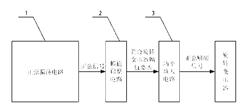
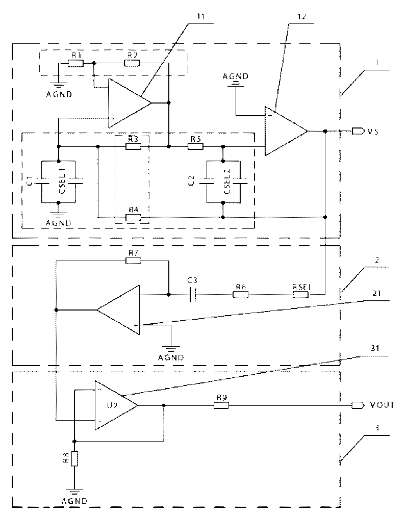
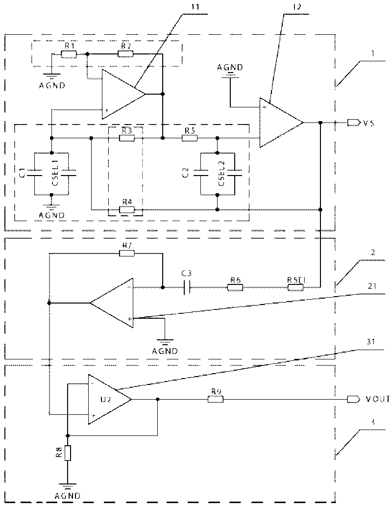
[0010] Specific implementation mode one: the following combination Figure 1-Figure 2 Describe this embodiment, this embodiment is made up of sinusoidal oscillation circuit 1, amplitude adjustment circuit 2 and power amplifying circuit 3, and sinusoidal oscillation circuit 1 is composed of resistance R1, resistance R2, resistance R3, resistance R4, resistance R5, capacitance C1, capacitance C2, capacitor CSEL1, capacitor CSEL2, the first operational amplifier 11 and the second operational amplifier 12, the amplitude adjustment circuit 2 is composed of resistor R6, resistor R7, resistor RSEL, capacitor C3 and the third operational amplifier 21, the power amplifier circuit 3 Composed of resistor R8, resistor R9 and power amplifier 31,

[0011] One end of the resistor R1 is connected to the analog ground, the other end of the resistor R1 is connected to the inverting input terminal of the first operational amplifier 11, and a resistor R2 is connected between the inverting input t...

specific Embodiment approach 2

[0028] Embodiment 2: The difference between this embodiment and Embodiment 1 is that the power amplifying circuit 3 also includes a resistor R9, one end of the resistor R9 is connected to the output end of the power amplifier 31, and the other end of the resistor R9 is the excitation power supply output of the circuit. Other components and connections are the same as those in Embodiment 1.

[0029] Resistor R9 is connected to the output terminal of power amplifier 31, and its resistance value can be selected within the range of tens of ohms. Crosstalk or signal reflection occurs.

specific Embodiment approach 3

[0030] Embodiment 3: The difference between this embodiment and Embodiment 1 or 2 is that the capacitors all use ceramic non-polar capacitors. Other compositions and connections are the same as those in the first or second embodiment.

[0031] Ceramic non-polar capacitors have a wide range of capacitance options and low prices, which is beneficial to frequency selection and reduces circuit costs.


PUM


Abstract

The invention discloses an excitation power circuit of a rotary transformer, belongs to the field of drive power sources, and solves the problems of complex circuit and incapability of independently working in the traditional excitation power of the rotary transformer. The excitation power circuit consists of a sinusoidal oscillation circuit, an amplitude adjusting circuit and a power amplifying circuit, wherein the sinusoidal oscillation circuit consists of a resistor R1, a resistor R2, a resistor R3, a resistor R4, a resistor R5, a capacitor C1, a capacitor C2, a capacitor CSEL1, a capacitor CSEL2, a first operational amplifier and a second operational amplifier; the amplitude adjusting circuit consists of a resistor R6, a resistor R7, a resistor RSEL, a capacitor C3 and a third operational amplifier; and the power amplifying circuit comprises a resistor R8 and a power amplifier. The frequency of a sinusoidal excitation power source generated by the circuit of the invention is modulated by selecting a capacitance value of the capacitor CSEL1 and the capacitor CSEL2, and the amplitude value of the sinusoidal excitation power source is adjusted by changing the resistance value of the resistor RSEL. The excitation power circuit of the invention serves as the drive power source of the rotary transformer.

Description

technical field [0001] The invention relates to an excitation power supply circuit of a rotary transformer, which belongs to the field of driving power supply. Background technique [0002] Resolvers are widely used in military products, robots, aerospace, mining and other industries as precise angle measurement due to their superior resistance to vibration, oil, water, high and low temperature, and long service life. device. The resolver is a passive device, and it must be excited by a sinusoidal drive power supply to generate analog position information output. Therefore, the frequency and amplitude of the sinusoidal excitation power supply and the distortion of the waveform directly affect the measurement accuracy of the resolver. [0003] There are three main ways to generate excitation power: In the early days, traditional analog passive devices were used to build an oscillating circuit with a certain frequency, and then a sinusoidal excitation power was generated thr...

Claims


Application Information

Patent Timeline
Patent Type & Authority Applications(China)
IPC IPC(8): H02M5/10
Inventor 介党阳倪风雷顾义坤党进张庆利郭闯强
Owner HARBIN INST OF TECH
Why Eureka
Try Eureka