Transmission mechanism of seeder

A transmission mechanism and seeder technology, applied in fertilization devices, applications, agriculture, etc., can solve the problems of affecting the seeding accuracy, non-rotation, and the speed change of the suppression roller blocking the speed change, so as to avoid uneven seeding density, simple structure of the transmission mechanism, The effect of reducing production costs

Inactive Publication Date: 2010-06-02
蒋宝华 +1
View PDF0 Cites 1 Cited by
  • Summary
  • Abstract
  • Description
  • Claims
  • Application Information

AI Technical Summary

Problems solved by technology

The problem with the first two methods is that the forward speed of the tractor is not synchronized with the rotational speed change of the gearbox (or cutter shaft) of the rotary cultivator. The rotary tillage speed of the cutter shaft does not change synchronously, so that the hole spacing becomes larger for the seeder, and the seed density becomes thinner for the drill, which affects the sowing accuracy
Although the third type overcomes the shortcomings of the above two types of asynchrony, it is synchronous at first glance. However, due to the changeable conditions in farmland operations, especially the current promotion of straw returning to the field in farmland, straw and wheat straw are often entangled on the suppression rollers. As a result, the pressing roller is stuck and cannot rotate continuously, or it slips on the straw and does not rotate, or when it encounters unevenness, the speed of the pressing roller will change or not turn when it is blocked, and the phenomenon of missing seeding and uneven seeding density still exists. Therefore, the above three methods all have some disadvantages in different degrees, which affect the quality of farmland sowing.

Method used


Image

  • Transmission mechanism of seeder
  • Transmission mechanism of seeder
  • Transmission mechanism of seeder

Examples


Embodiment Construction

[0017] The present invention will be described in detail below in conjunction with the accompanying drawings.

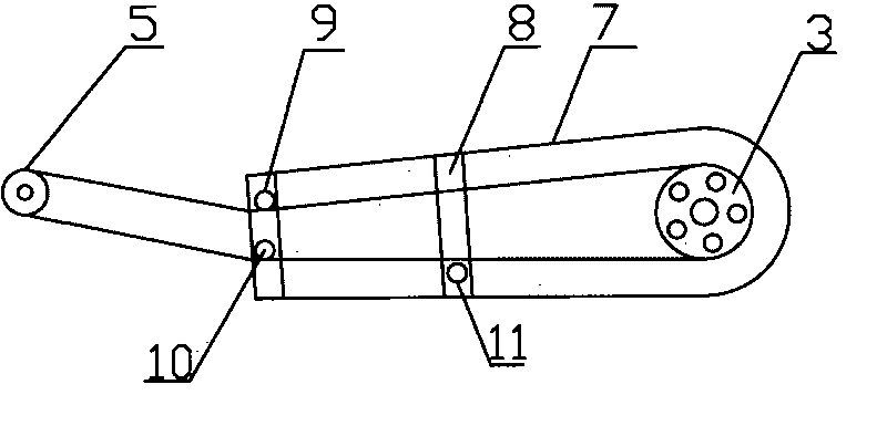
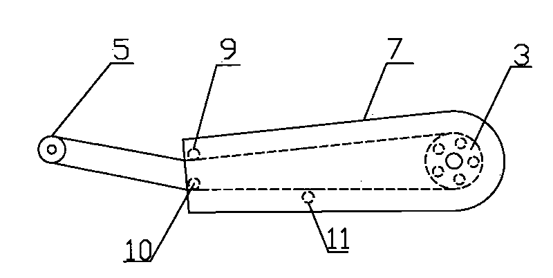
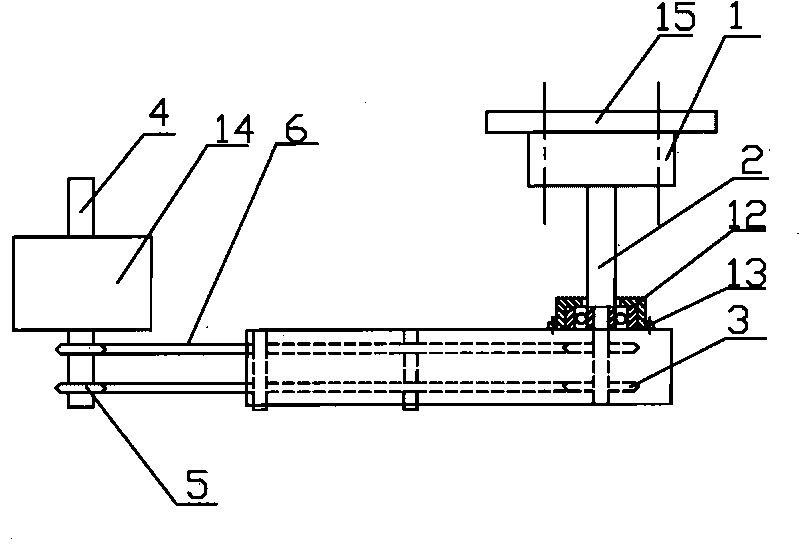
[0018] like figure 1 , figure 2 shown, combined with image 3 . A planter transmission mechanism matched with large and medium-sized tractors, comprising a connection device 1, an input drive shaft 2 fixedly connected to the connection device 1, a first sprocket 3 fixedly connected to the input drive shaft 2, and a seeder main shaft for speed change The output drive shaft 4 connected by box transmission, the second sprocket wheel 5 mounted on the output drive shaft 4 and the chain 6 mounted on the first sprocket wheel 3 and the second sprocket wheel 5 form. The connecting device 1 is fixedly connected with the wheel hoop of the large and medium-sized tractor, which can be a flange, or a shaft, or a shaft sleeve, or a spline; the first sprocket 3, the second sprocket 5 and the chain 6. It consists of multiple pairs; at least one set, that is, a first sprocket 3, ...


PUM


Abstract

The invention discloses a transmission mechanism of a seeder, which comprises an input transmission shaft, a first sprocket wheel, an output transmission shaft, a second sprocket wheel and a chain. The first sprocket wheel is arranged on the input transmission shaft; the second sprocket wheel is arranged on the output transmission shaft; and the chain is arranged on the first and the second sprocket wheels. The transmission mechanism of the seeder is characterized in that: the input transmission shaft is connected with the wheel hub of a tractor rotating wheel; the output transmission shaft is connected with the main shaft gearbox of the seeder; and the chain is provided with a floating tension device. In the transmission mechanism of the seeder of the invention, the input transmission shaft is connected with the transmission mechanism which enables the tractor to go forward, and the transmission chain is provided with the floating tension device which is used for tensioning the loosened chain at the traction section to realize the tension control for the chain, so the synchronization of the input and the output transmission shafts is ensured, the phenomena of miss-seeding and non-uniform seeding density are avoided, and the seeding quality of the farmland is increased.

Description

technical field [0001] The invention relates to a seeder transmission mechanism matched with a large and medium-sized tractor, belonging to the field of agricultural seeding machinery manufacturing. Background technique [0002] At present, the way that my country's agricultural seeding machinery is matched with large and medium-sized tractors is to install a seeder above the rotary tiller suspended at the rear of the tractor. There are several power transmission methods: one is to extend a shaft from the gearbox of the rotary tiller The head is transmitted to the main shaft of the seeder through a sprocket and a chain; the other is to be transmitted from one end of the shaft head of the rotary tiller to the main shaft of the seeder through a sprocket and a chain; the third is to place a The suppression roller drives the main shaft of the seeder to rotate through the sprocket and chain on the shaft head of the suppression roller. The problem with the first two methods is that...

Claims


Application Information

Patent Timeline
Patent Type & Authority Applications(China)
IPC IPC(8): A01C19/04
Inventor 蒋宝华孙加林
Owner 蒋宝华
Why Eureka
Try Eureka