Double-crucible directional solidification device

A directional solidification, double crucible technology, applied in measuring devices, instruments, scientific instruments, etc., can solve the problems of difficult cutting, different temperature fields of melts, different axes of heating bodies, etc., to reduce the difficulty of cutting and use. Convenience and low cost effect

Inactive Publication Date: 2010-06-02
NORTHWESTERN POLYTECHNICAL UNIV
View PDF0 Cites 5 Cited by
  • Summary
  • Abstract
  • Description
  • Claims
  • Application Information

AI Technical Summary

Problems solved by technology

However, since the crucibles of various diameters in the prior art are not coaxial when bundled together, and are also not coaxial with the heating element, this causes the temperature field of the melt in each crucible to be different, which has a certain impact on the microstructure
At the same time, since there are many corundum tubes embedded in the sample, it is difficult to cut the sample after the directional solidification experiment.

Method used


Image

  • Double-crucible directional solidification device
  • Double-crucible directional solidification device
  • Double-crucible directional solidification device

Examples


Embodiment 1

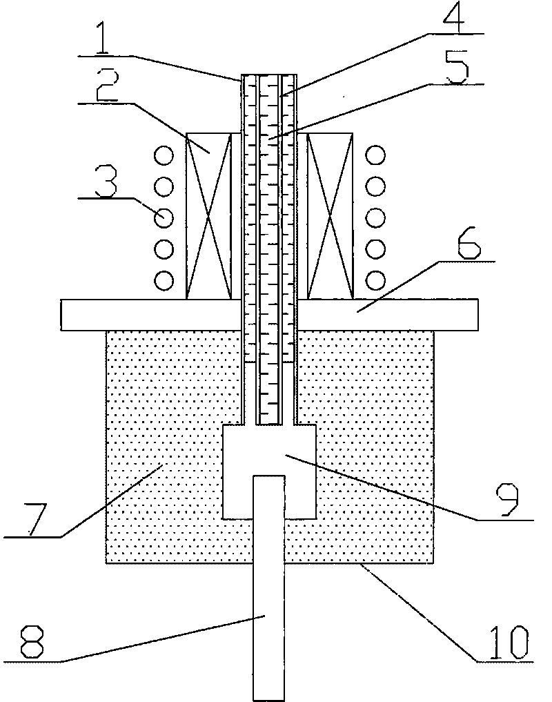
[0020] This embodiment is a double-crucible directional solidification device for lead-bismuth alloy samples.

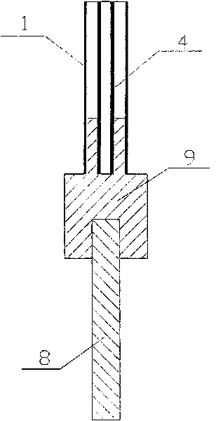
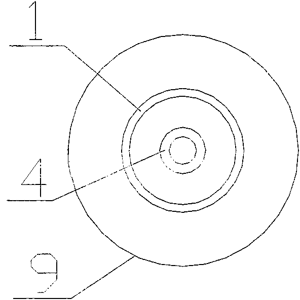
[0021] This embodiment includes a large crucible 1, a graphite heating element 2, an induction coil 3, a small crucible 4, a sample 5, a heat shield 6, a liquid Ga-In-Sn alloy 7, a pull rod 8, a joint 9 and a cooler 10, Wherein, the heat insulation board 6 is located at the upper end of the cooler 10, and the joint 9 is located in the cooler 10; one end of the drawing rod 8 is located in the cooler 10, and is connected with one end of the joint 9, and the other end of the drawing rod 8 passes through the bottom plate of the cooler 10. The drawing hole is located outside the cooler 10. The small crucible 4 is nested in the large crucible 1, and the two crucibles are coaxial to form a double crucible. One end of the double crucible is located in the cooler 10 and connected to the other end of the joint 9 ; the other end of the double crucible passes through the via ho...

Embodiment 2

[0029] This embodiment is a double-crucible directional solidification device for aluminum-copper alloy samples.

[0030] This embodiment includes a large crucible 1, a graphite heating element 2, an induction coil 3, a small crucible 4, a sample 5, a heat shield 6, a liquid Ga-In-Sn alloy 7, a pull rod 8, a solidified sample 9, and a joint 9 And the cooler 10, wherein, the heat shield 6 is located at the upper end of the cooler 10, and the joint 9 is located in the cooler 10; one end of the drawing rod 8 is located in the cooler 10, and is connected with one end of the joint 9, and the other end of the drawing rod 8 passes through the cooling The drawing hole on the base plate of the cooler 10 is located outside the cooler 10. The small crucible 4 is nested in the large crucible 1, and the two crucibles are coaxial to form a double crucible. One end of the double crucible is located in the cooler 10 and connected to the other end of the joint 9 ; the other end of the double ...

Embodiment 3

[0038] This embodiment is a double-crucible directional solidification device for Ni-base superalloy samples.

[0039] This embodiment includes a large crucible 1, a graphite heating element 2, an induction coil 3, a small crucible 4, a sample 5, a heat shield 6, a liquid Ga-In-Sn alloy 7, a pull rod 8, a joint 9, a joint 9 and cooling The heat shield 6 is located at the upper end of the cooler 10, and the joint 9 is located in the cooler 10; one end of the drawing rod 8 is located in the cooler 10 and is connected with one end of the joint 9, and the other end of the drawing rod 8 passes through the cooler 10 The drawing hole on the base plate is located outside the cooler 10 . The small crucible 4 is nested in the large crucible 1, and the two crucibles are coaxial to form a double crucible. One end of the double crucible is located in the cooler 10 and connected to the other end of the joint 9 ; the other end of the double crucible passes through the via hole in the center...


PUM

PropertyMeasurementUnit
thicknessaaaaaaaaaa
heightaaaaaaaaaa
heightaaaaaaaaaa

Abstract

The invention relates to a double-crucible directional solidification device. A crucible comprises a big crucible (1) and a small crucible (4), wherein the small crucible (4) is nested in the big crucible (1); the big crucible (1) and the small crucible (4) are coaxial and form a double crucible; one end of the double crucible is positioned in a cooler (10) and is connected with the other end of a joint (9); and the other end of the double crucible penetrates through a through hole in the center of a heat insulation plate (6) and is arranged in an induction coil (3). In the invention, the temperature fields of fusants in the two coaxial crucibles are consistent, and a condition that test bars with different diameters are drawn and pulled simultaneously under the same experimental parameter is provided. Compared with the prior art, the invention eliminates the influence of different temperature fields on the directional solidification microstructures of samples, is more suitable for researching the influence of the convection of the fusants on the microstructures in a directional solidification process and has the characteristics of convenient use and low cost.

Description

1. Technical field [0001] The invention relates to the field of directional solidification of materials, in particular to a double-crucible directional solidification device. 2. Background technology [0002] In the directional solidification experiment, the microstructure of the sample plays a very important role in the final performance of the material, such as the influence of the primary dendrite spacing of directional growth on the mechanical properties of the alloy. The primary dendrite spacing of the directional growth microstructure is not only directly affected by the solidification parameters, but also related to the convection of the melt in the crucible. Therefore, it is necessary to study the effect of melt convection on the primary dendrite spacing during directional solidification. [0003] The effect of convection on primary dendrite spacing is studied according to the strength of convection of the melt in crucibles with different diameters. Usually, samples...

Claims


Application Information

Patent Timeline
Patent Type & Authority Applications(China)
IPC IPC(8): G01N25/00
Inventor 胡小武李双明高斯峰刘林傅恒志
Owner NORTHWESTERN POLYTECHNICAL UNIV
Why Eureka
Try Eureka