Ceramic insulator and high voltage power capacitor insulator device

A technology of ceramic insulators and high-voltage power, applied in capacitors, insulators, lead-in/through-type insulators, etc., can solve the problems of cumbersome processing and installation operations, achieve good installation and operation, and ensure the aesthetic effect of the appearance

Active Publication Date: 2010-06-02
STATE GRID CORP OF CHINA +3
View PDF1 Cites 36 Cited by
  • Summary
  • Abstract
  • Description
  • Claims
  • Application Information

AI Technical Summary

Problems solved by technology

[0005] During the follow-up R&D and trial production process, the applicant found that two semi-circular metal retaining rings are welded and fixed to the metal mounting seat, so as to ensure that the metal mounting seat is firmly fixed on the ceramic outer wall. This structure is feasible and can meet the requirements of the national Relevant standards, but the operation process of its processing and installation is relatively cumbersome, and it is necessary to use a special special fixture to clamp the metal retaining ring and the metal mounting seat, so that it can be welded smoothly

Method used


Image

  • Ceramic insulator and high voltage power capacitor insulator device
  • Ceramic insulator and high voltage power capacitor insulator device
  • Ceramic insulator and high voltage power capacitor insulator device

Examples


Embodiment 1

[0030] (Example 1, ceramic insulator)

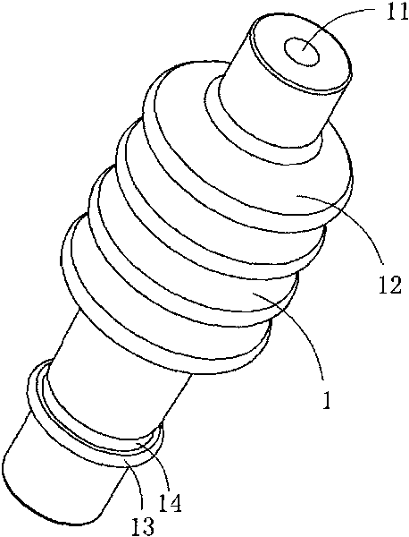
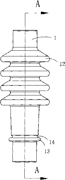
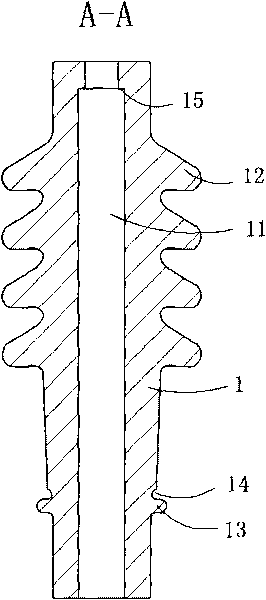
[0031] Figure 1 to Figure 3 A specific embodiment of the ceramic insulator of the present invention is shown, wherein, figure 1 It is a schematic diagram of a three-dimensional structure of a ceramic insulator in the present invention; figure 2 yes figure 1 Front view of the ceramic insulator shown; image 3 yes figure 2 The cross-sectional view of the shown ceramic insulator along line A-A.

[0032] This embodiment is a ceramic insulator for high voltage capacitors, see Figure 1 to Figure 3 , including a ceramic insulator body 1; the ceramic insulator body 1 is provided with a through hole 11 along its central axis, a plurality of sheds 12 are provided on the outer wall of the middle part of the insulator body 1, and a plurality of sheds 12 are provided on the outer wall of the lower part of the insulator body 1. There is an annular positioning boss 13 ; the insulator body 1 is also provided with an annular groove 14 between t...

Embodiment 2

[0035] (Example 2, High Voltage Power Capacitor Insulator Device)

[0036] Figure 4 to Figure 7 A specific embodiment of the high voltage power capacitor insulator device of the present invention is shown, wherein Figure 4 It is a three-dimensional structural schematic diagram of the first structure of the medium and high voltage power capacitor insulator device of the present invention; Figure 5 yes Figure 4 The schematic diagram of the three-dimensional structure of the high-voltage power capacitor insulator device when viewed from another angle; Figure 6 yes Figure 4 An exploded view of the shown high-voltage power capacitor insulator device; Figure 7 yes Figure 4 A half-section structural view of the high-voltage power capacitor insulator device shown.

[0037] This embodiment is a high-voltage power capacitor insulator device, see Figure 4 to Figure 7 , including a ceramic insulator body 1, a wiring assembly 2 arranged at the top of the ceramic insulator bod...


PUM


Abstract

The invention discloses a ceramic insulator and a high voltage power capacitor insulator device. The ceramic insulator comprises a ceramic insulator body, wherein the middle outer wall is provided with a plurality of umbrella skirts, and the lower wall is provided with an annular locating lug boss; and an annular groove is arranged between the annular locating lug boss and the umbrella skirts. The insulator device comprises the ceramic insulator body, a wiring assembly and a mounting assembly; the mounting assembly comprises a metal mounting seat and a seal ring; the metal mounting seat is tubular, the upper end of the metal mounting seat is provided with a welding part, the lower end is provided with a blocking part, and the blocking part is positioned below the annular locating lug boss; the seal ring is positioned between the lower surface of the annular locating lug boss and the blocking part; the welding part is higher than the annular groove of the insulator body; and the inner wall of the welding part of the metal mounting seat, the outer wall of the insulator body and the annular locating lug boss enclose a welding space, and welding flux is arranged in the welding space. The invention is convenient to mount and operate and effectively enhances the production efficiency.

Description

technical field [0001] The invention relates to the technical field of ceramic insulator structure design, in particular to a ceramic insulator and a high-voltage power capacitor insulator device made of the ceramic insulator. Background technique [0002] The ceramic insulators of high-voltage capacitors currently on the market use silver to weld the mounting part and the ceramic body together to make it firmly fixed on the ceramic body. This product has high cost, cumbersome steps, and long processing time. [0003] Traditional ceramic insulators need to weld metal wiring components and mounting components to the body of the ceramic insulator. Due to the particularity of ceramics, special solder with silver alloy as the main component needs to be used. This solder is very expensive. To ensure the firmness of the combination of the two, a relatively thick solder layer is required, and more materials are used, resulting in high cost of this kind of insulator; in addition, in...

Claims


Application Information

Patent Timeline
Patent Type & Authority Applications(China)
IPC IPC(8): H01B17/00H01B17/26H01B17/30H01G2/00
Inventor 王海龙
Owner STATE GRID CORP OF CHINA
Why Eureka
Try Eureka