Quasi-level-switching device of multi-quasi-level power supply converter

A technology for outputting power supply and switching device, which is applied in the direction of output power conversion device, DC power input conversion to DC power output, instruments, etc., can solve the problems of slow change speed, inconvenient chip, etc., to improve overshoot or undershoot the effect of the situation

Inactive Publication Date: 2013-08-14
RICHTEK TECH
View PDF4 Cites 0 Cited by
  • Summary
  • Abstract
  • Description
  • Claims
  • Application Information

AI Technical Summary

Problems solved by technology

[0005] At present, there are many ways to reduce the undershoot and overshoot. The most common methods include reducing the inductance L to reduce the energy stored in the inductance L, increasing the capacitance Cout to slow down the change speed of the output voltage Vout and increasing the low voltage. The pass filter reduces the ripple change of the feedback signal VFB, but these methods are adjusted by the outside of the chip
[0006] Therefore, there are above-mentioned inconveniences and problems in the known method of adjusting outside the chip.

Method used


Image

  • Quasi-level-switching device of multi-quasi-level power supply converter
  • Quasi-level-switching device of multi-quasi-level power supply converter
  • Quasi-level-switching device of multi-quasi-level power supply converter

Examples


Embodiment Construction

[0058] The present invention will be further described below in conjunction with embodiment and accompanying drawing.

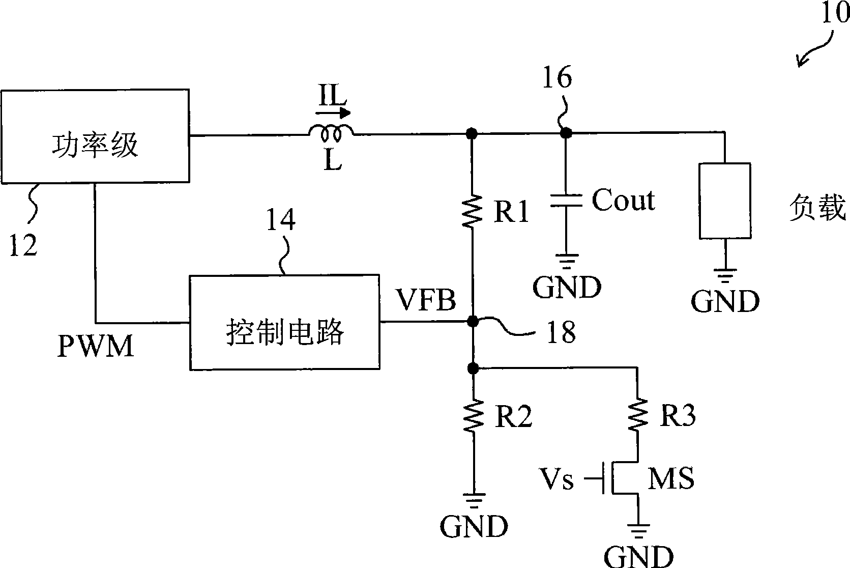
[0059] see now Figure 4 , Figure 4 It is a schematic diagram of the first embodiment of the present invention. As shown in the figure, in the multi-level output power converter 40, the control circuit 44 generates a pulse width modulation signal PWM to drive the power stage 42 according to the feedback signal VFB to generate an inductor current IL to charge the capacitor Cout to generate an output voltage Vout, The level switching device 50 is used for switching the output voltage level of the power converter 40 . In the potential switching device 50, the voltage divider circuit 54 divides the output voltage Vout to generate a feedback signal VFB, and the feedback signal VFB is output by the feedback terminal 48 of the voltage divider circuit 54, and the resistor R3 and the NMOS transistor MS are connected in series at the feedback terminal 48 and grounde...


PUM


Abstract

The invention relates to an electric potential switching device of a multi-level output power supply converter, comprising a divider circuit, a resistor, an MOS transistor and an undershoot overshoot eliminator and characterized in that the divider circuit obtains a feedback signal which is relevant to an output signal of the output end at the output end of the multi- level output power supply converter; the divider circuit comprises a feedback end from which the feedback signal is output; the resistor and the MOS transistor are connected in series between the feedback end and the grounding end; and the undershoot overshoot eliminator is arranged in the electric potential switching device for adjusting the switching speed of the MOS transistor from full open to full close or from full close to full open. The electric potential switching device of the multi-level output power supply converter has the advantage that the undershoot or overshoot conditions of the output signal are improved.

Description

technical field [0001] The invention relates to a multi-level output power converter, in particular to a potential switching device for a multi-level output power converter. Background technique [0002] figure 1 A known power converter 10 that can change the output potential is shown, which includes a control circuit 14 that provides a signal PWM to drive the power stage 12 to generate an inductor current IL that charges the capacitor Cout through the inductor L to generate an output voltage Vout, and the resistor R1 is connected to the output terminal 16 between the feedback terminal 18 and the feedback terminal 18, the resistor R2 is connected between the feedback terminal 18 and the ground terminal GND, the resistor R3 and the switch MS are connected in series between the feedback terminal 18 and the ground terminal GND, and the control circuit 14 according to the feedback signal VFB on the feedback terminal 18 Generate signal PWM. Among them, the feedback signal VFB c...

Claims


Application Information

Patent Timeline
Patent Type & Authority Patents(China)
IPC IPC(8): H02M3/157H02M3/139
Inventor 张乔杰王克丞
Owner RICHTEK TECH
Why Eureka
Try Eureka