Band gap reference circuit with transient enhancing function

A reference circuit and reference technology, applied in the direction of adjusting electrical variables, control/regulating systems, instruments, etc., can solve the problems of long transient response time of the circuit, breakdown of circuit tubes, large grid capacitance, etc., to improve the jitter problem, Improve the effect of overshoot problem

Active Publication Date: 2018-09-18
UNIV OF ELECTRONICS SCI & TECH OF CHINA
View PDF8 Cites 0 Cited by
  • Summary
  • Abstract
  • Description
  • Claims
  • Application Information

AI Technical Summary

Problems solved by technology

However, in the traditional reference source, when the reference circuit is started, the reference voltage and current have a large overshoot because the reference loop has not been established, which will cause some tubes in the circuit to have a risk of breakdown. When the circuit involves a sudden change in load When the size of the power MOS is generally large, the gate capacitance is large, so the transient response time of the circuit is long, which seriously affects the circuit performance.

Method used


Image

  • Band gap reference circuit with transient enhancing function
  • Band gap reference circuit with transient enhancing function
  • Band gap reference circuit with transient enhancing function

Examples


Embodiment Construction

[0023] The technical solution of the present invention will be described in detail below in conjunction with the accompanying drawings and specific embodiments.

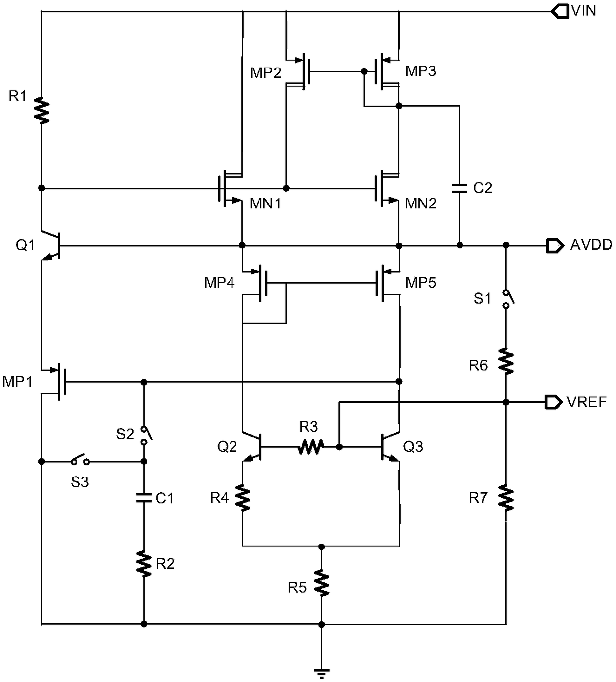
[0024] Such as figure 1 Shown is a structural schematic diagram of a bandgap reference circuit with transient enhancement provided by the present invention, including a bandgap reference module, a transient enhancement module and a slow start module, and the bandgap reference module is a Brokaw type reference, including a first NMOS transistor MN1, the second NMOS transistor MN2, the fourth PMOS transistor MP4, the fifth PMOS transistor MP5, the second transistor Q2, the third transistor Q3, the third resistor R3, the fourth resistor R4, the fifth resistor R5, the Six resistors R6 and seventh resistor R7, the gate of the first NMOS transistor MN1 is connected to the gate of the second NMOS transistor MN2, its drain is used as the input end of the bandgap reference circuit, and its source is connected to the second NM...


PUM


Abstract

The invention discloses a band gap reference circuit with a transient enhancing function, and belongs to the technical field of electronic circuits. The band gap reference circuit comprises a band gapreference module, a transient enhancing module and a slow-start module. The Brokaw type reference is adopted for the band gap reference module, and the reference voltage errors caused by base currents of a second triode and a third triode can be counteracted through a third resistor; dynamic current bias is formed with the transient enhancing module and a second NMOS tube in the band gas reference module through a second PMOS tube and a third PMOS tube, and the transient response of a circuit is optimized; meanwhile, transient charging currents of a grid of a first NMOS tube are increased through dynamic currents provided by a current mirror formed with a second capacitor, the second PMOS tube and the third PMOS tube; a feed loop is formed with the second capacitor, the second PMOS tube and the third PMOS tube, and great dropping of power supply voltages is avoided; voltages of a grid of the first PMOS tube are slowly increased by the slow-start module through a first switch, a secondswitch, a third switch and a first capacitor, and the overshoot of voltages and currents in the loop establishing process is avoided.

Description

technical field [0001] The invention relates to electronic circuit technology, in particular to a bandgap reference circuit with transient enhancement. Background technique [0002] The reference source is an indispensable module in common power management chips such as DC / DC converters, AC / DC converters, charging protection chips, LED drivers, linear voltage regulators, and PWM modulators. The module provides a reference voltage, and the accuracy and stability of the reference source will directly affect the performance of the chip, so it is particularly important to design a high-performance reference source. However, in the traditional reference source, when the reference circuit is started, the reference voltage and current have a large overshoot because the reference loop has not been established, which will cause some tubes in the circuit to have a risk of breakdown. When the circuit involves a sudden change in load When the size of the power MOS is generally large, t...

Claims


Application Information

Patent Timeline
Patent Type & Authority Applications(China)
IPC IPC(8): G05F1/56
CPCG05F1/56
Inventor 李泽宏熊涵风洪志超赵念张成发罗仕麟
Owner UNIV OF ELECTRONICS SCI & TECH OF CHINA
Why Eureka
Try Eureka