Cantilever type overflow weir

An overflow weir and cantilever type technology, which is applied in the direction of distillation separation, fractionation, chemical instruments and methods, etc., can solve the problem of resonance between fluid and equipment, the influence of uniformity of flow field distribution on the tray, and the transformation of ordinary downcomers Inapplicable and other problems, to achieve the effect of improving the amplification effect, ensuring full contact mass transfer, efficient and stable mass transfer efficiency

Active Publication Date: 2012-02-29
BC P INC CHINA NAT PETROLEUM CORP +1
View PDF4 Cites 0 Cited by
  • Summary
  • Abstract
  • Description
  • Claims
  • Application Information

AI Technical Summary

Problems solved by technology

[0008] (1) When the liquid overflows and crosses the weir, a liquid "waterfall" will be formed, and the gas separated from the liquid in the downcomer will be encapsulated and cannot be discharged, and a gas cavity will be formed behind the weir plate, making the liquid flow easy to flow in the downcomer The mouth of the liquid pipe will form a thimble, which cannot flow down normally, which will also cause the downcomer to flood (see figure 1 )
[0009] (2) Ordinary flat plate structure also has a significant impact on the uniformity of flow field distribution on the plate
[0010] (3) When using a conventional weir, if the operating gas velocity is low, the leakage of the liquid on the tray plate through the bubbling element is large, and the liquid is blocked by the weir plate, and the liquid will not be able to cross the weir to form an overflow
These improvement measures have a certain effect on improving a certain performance of the tray or downcomer, but because there is no discharge port between the overflow weir and the outlet of the tray, it cannot solve the problem of resonance between the fluid and the equipment at the lower limit of operation; and the liquid on the weir The height of the head is high, and the fluctuation on the tray is aggravated, which is not conducive to stable operation; these patented weirs generally must adopt a matching downcomer structure, which is not suitable for the equipment transformation of ordinary downcomers

Method used


Image

  • Cantilever type overflow weir
  • Cantilever type overflow weir
  • Cantilever type overflow weir

Examples


Embodiment Construction

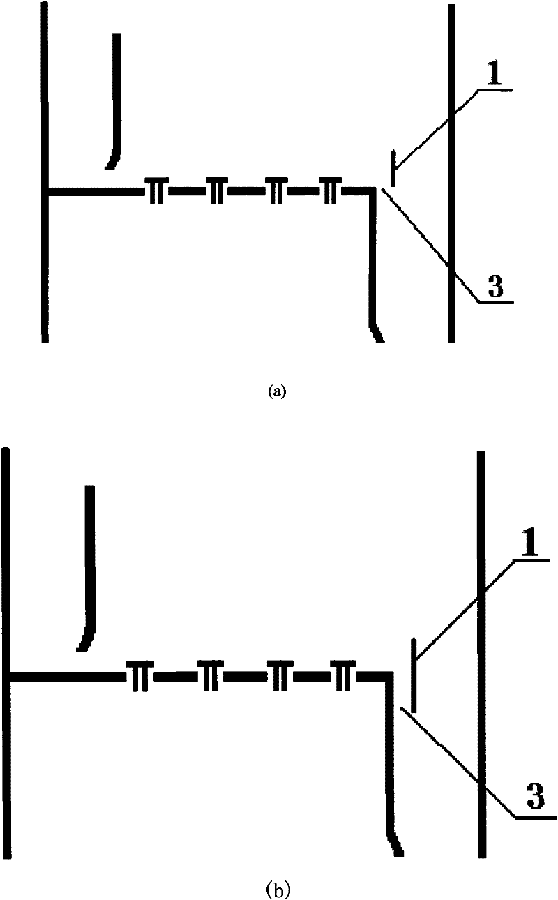
[0039] The invention relates to a cantilever overflow weir, refer to image 3 and Figure 4 As shown, it includes the weir plate 1, the cantilever 2, the tray overflow port 3 and the weir plate opening 4, and there is a strip tray overflow port 3 between the weir plate 1 and the tray outlet, and the weir plate 1 and the cantilever 2 Connected to extend into the downcomer, the weir plate 1 is provided with a weir plate opening 4 .

[0040] like image 3 As shown, the lower edge of the weir plate 1 is flush with or lower than the tray plate, and the height of the weir plate is related to the liquid flow intensity, operating pressure and upper limit of the processing capacity. The shape of the upper edge of the weir plate 1 can be straight, and can also be bow-shaped, trapezoidal, tooth-shaped or other non-straight structures, and the configuration is as follows Figure 5 shown. The weir itself of the weir plate 1 can be a straight plate, or it can be arc-shaped, bow-shaped o...


PUM


Abstract

The invention relates to a cantilever type overflow weir, which comprises a weir plate, a cantilever, a tray overflow port and a weir plate opening. The weir plate is connected with the cantilever and stretches into a downspout; and the tray overflow port is formed between the weir plate and a tray outlet. The structure can eliminate resonance formed by fluid and a tower device at a low air speed, damage the fluctuation of a liquid layer on the plate, expand lower limit for operation and increase the elastic range by 5 to15 percent; when a liquid level is small, liquid flow directly enters the downspout from the tray overflow port without throwing beyond the weir so as not to form an air cavity in the downspout; when the liquid level is large, liquid overflows from the tray overflow port and the weir plate to reduce the height of liquid head on the weir by splitting the liquid; thus the liquid flow on the plate more tends to be plug flow to relieve retention and back-mixing; two streams of liquid flow interact in the downspout to help the gas liberation; the weir plate opening on the weir plate can discharge part of the liquid. The cantilever type overflow weir has a simple structure, can improve the operational stability of the tray and the downspout and is applicable to various liquid levels.

Description

technical field [0001] The present invention relates to an overflow weir mainly used in tray towers in the petroleum and chemical processing industries. Background technique [0002] The overflow weir is an important internal component of the tray tower. Conventional overflow weirs are directly installed at the outlet of the tray, which can maintain a certain thickness of liquid layer on the tray, so that the rising vapor phase can fully contact and mass transfer with the liquid phase flowing on the tray. Although the structure of the overflow weir is simple, it has a significant impact on the processing capacity, operational stability, and mass transfer efficiency of the tray and downcomer. [0003] At present, the flat weir is the most widely used in the industry. The weir plate is a straight plate with a straight upper edge; when the liquid phase load is low, a toothed weir can also be used to ensure uniform liquid on the plate under low liquid volume. flow. In additio...

Claims


Application Information

Patent Timeline
Patent Type & Authority Patents(China)
IPC IPC(8): B01D3/18B01D3/20
Inventor 刘艳升曹睿严超宇刘拥军
Owner BC P INC CHINA NAT PETROLEUM CORP
Why Eureka
Try Eureka