Two-die three-punch upsetter and working method

An upsetting machine and upsetting technology are applied in the field of a new type of two-die three-blow upsetting machine, which can solve the problems that it is difficult to form a trimmed outer hexagon trimmed bolt workpiece, a cylindrical head inner hexagonal grooved bolt workpiece, and cannot be formed.

Inactive Publication Date: 2010-06-09
杨东佐
View PDF0 Cites 38 Cited by
  • Summary
  • Abstract
  • Description
  • Claims
  • Application Information

AI Technical Summary

Problems solved by technology

The two-die three-blow upsetting machine with this structure is difficult to form trimmed outer hexagonal trimmed bolt workpieces, cylindrical

Method used


Image

  • Two-die three-punch upsetter and working method
  • Two-die three-punch upsetter and working method
  • Two-die three-punch upsetter and working method

Examples


Embodiment 1

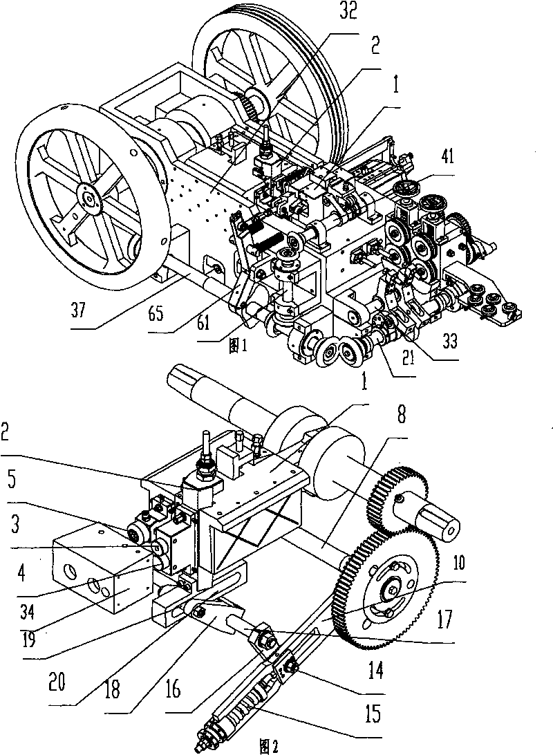
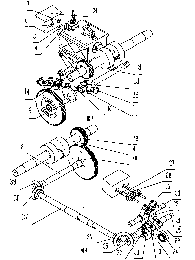
[0061] Such as figure 1 , figure 2 , image 3 As shown, a two-die three-punch upset forging machine includes a feeding mechanism, a material shearing mechanism, a material delivery mechanism, a die assembly, a die assembly, an ejector mechanism, a large slide block 1 for installing the die assembly and can be used in a large The lifting plate 2 reciprocating up and down in the slider 1, the driving mechanism of the large slider 1, and the driving mechanism of the lifting plate 2. The die assembly includes a first die 3 , a second die 4 and a third die 5 . The third punching die 5 is a forging punching die for forming a cylindrical head inner hexagon groove-shaped workpiece. The third punching die 5 is installed on the large slider 1 , and the first punching die 3 and the second punching die 4 are installed on the lifting plate 2 . The die assembly includes a first die 6 and a second die 7 installed in the die holder 34, the first die 6 corresponds to the first die 3 and th...

Embodiment 2

[0082] Such as Figure 13 to Figure 17 As shown, different from Embodiment 1, the third die 101 is a trimming die; the ejector mechanism includes a camshaft 102, a camshaft driving mechanism, a first cam 103 and a second cam 111 fixed on the camshaft 102, The first mandrel rocker 104, the first roller 112 installed on the first mandrel rocker, the second mandrel rocker 105, the second roller 113 installed on the second mandrel rocker 105, can be connected with the first mandrel mandrel The first ejector mechanism 106 to which 104 abuts, and the second ejector mechanism 107 which can be abutted to the second ejector rocker 105 . The first roller 112 abuts against the first cam 103 , and the second roller 113 abuts against the second cam 111 . The first push rod rocker 104 and the second push rod rocker 105 are rotatably pivoted on the push rod rocker shaft 108 fixed with the body; the first push rod mechanism 106 cooperates with the first die 109, and the second push rod mecha...

Embodiment 3

[0097] Such as Figure 18 As shown, different from Embodiment 1, the shearing mechanism includes a shearing bar 250, a shearing bar driving mechanism, a shearing knife 251 fixed on the shearing bar 250, and a wire 252 is arranged on the shearing knife 251. Diametrically matched cylindrical housing holes; the clamp delivery mechanism is a double clamp mechanism, including a first clamp that clamps the blank in the shear position, pushes the blank from the shear knife and delivers it to the first die position Mechanism 253, the second clamp mechanism 254 that delivers the workpiece that has been forged twice from the first die position to the second die position.

[0098] Such as Figure 19 As shown, the upsetting machine also includes a blank ejection mechanism. The blank ejection mechanism includes the top blank cam 256 fixed on the cam shaft 255, the top blank rocker 258 pivotally connected to the rocker shaft 257 fixed with the body, the roller 259 installed on the top bla...


PUM


Abstract

The invention relates to a two-die three-punch upsetter. A third punch die is a trimming die or a forging and pressing die and is arranged on a large slide block, and a first punch die and a second punch die are arranged on a lifting plate; a first concave die corresponds to the first punch die and the second punch die, and a second concave die corresponds to the third punch die; and axis of the second concave die and the third punch die are oppositely kept on the same straight line all the time. A working method comprises the following steps of: forming a workpiece by rotating a crank shaft twice; when the large slide block is upset for the first time, upsetting a blank into a primary upsetting semi-finished workpiece by the first punch die and preserving the semi-finished workpiece in the first concave die; upsetting a secondary upsetting semi-finished workpiece into a finished workpiece by the third die and ejecting the finished workpiece out; when the large slide block upsets for the second time, upsetting the primary upsetting semi-finished workpiece into the secondary upsetting semi-finished workpiece by the second punch die and ejecting the secondary upsetting semi-finished workpiece out; and air beating by the third punch die. The invention can achieve the functions of various upsetters, such as a one-die two-punch upsetter, an outer hexangular trimming machine, a three-die three-punch upsetter, and the like.

Description

technical field [0001] The present invention relates to a kind of upsetting forging machine and working method, especially relate to a kind of new-type two-mold three-stroke upsetting and forging machine and working method that can form trimmed outer hexagonal trimming bolt workpiece, cylindrical head inner hexagonal grooved bolt workpiece. Background technique [0002] An existing upsetting machine for forming trimmed outer hexagonal trimmed bolt workpieces comprises a one-die two-blow upsetting machine and a trimmed outer hexagonal trimming machine. This kind of heading and forging machine for forming and trimming outer hexagon trimming bolt workpiece head and trimming outer hexagon trimming process needs to use two sets of equipment to complete the head and hexagon trimming process, the equipment cost is high, the production efficiency is low, and the equipment It takes up a lot of space, and both human resources and energy are wasted. [0003] There is also a kind of up...

Claims


Application Information

Patent Timeline
IPC IPC(8): B21K1/46B21K1/54B21J13/14B21K27/02B21K27/06
CPCB21J9/06B21K1/463B21J9/022
Inventor 杨东佐
Owner 杨东佐
Why Eureka
Try Eureka