
Injection molding method for manufacturing light panel

A technology of injection molding and light guide plate, used in optical components, other household appliances, household appliances, etc., can solve the problems of high quality, thick thickness of the light guide plate, not suitable for light and thin products, etc.

Inactive Publication Date: 2010-06-09
HONG FU JIN PRECISION IND (SHENZHEN) CO LTD +1
View PDF0 Cites 1 Cited by
  • Summary
  • Abstract
  • Description
  • Claims
  • Application Information

AI Technical Summary

Problems solved by technology

[0003] However, the injection speed and injection pressure of the traditional injection molding machine are relatively low, and the thickness of the molded light guide plate is relatively thick, which makes the backlight module using the light guide plate large in size and high in quality, which is not suitable for light and thin products.

Method used


Image

  • Injection molding method for manufacturing light panel
  • Injection molding method for manufacturing light panel
  • Injection molding method for manufacturing light panel

Examples


Embodiment Construction

[0012] Embodiments of the present invention will be described in detail below in conjunction with the accompanying drawings.

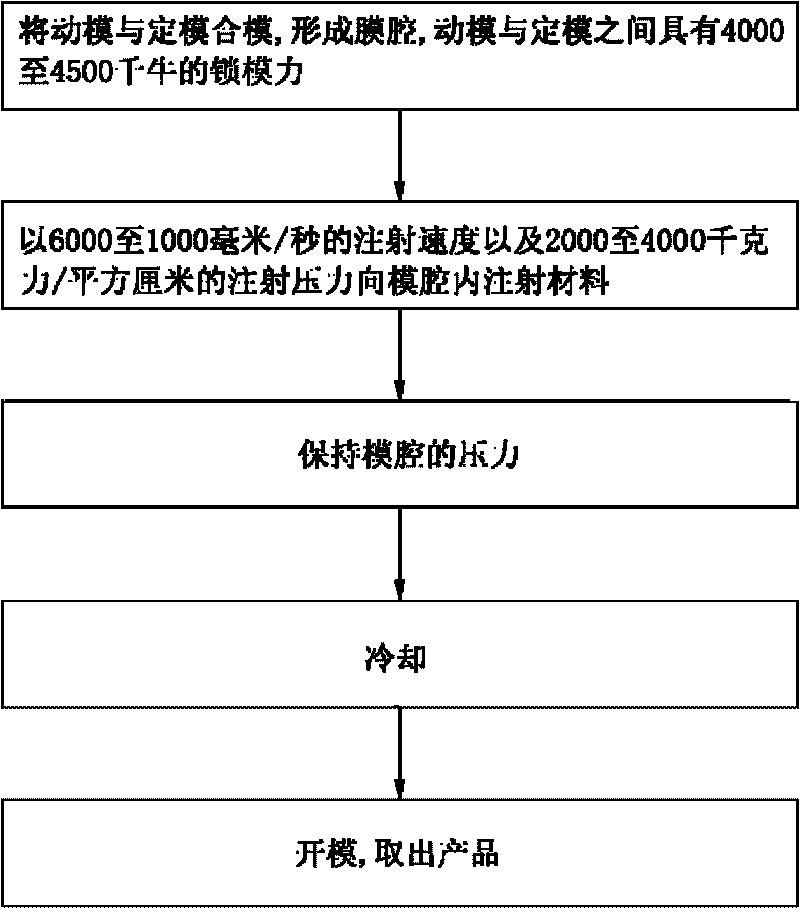
[0013] Such as figure 1 As shown, the method for manufacturing a light guide plate by injection molding according to the embodiment of the present invention mainly includes the following steps:

[0014] Clamp the movable mold with the fixed mold to form a mold cavity, with a clamping force of 4000 to 4500 kN between the movable mold and the fixed mold;

[0015] Inject material into the mold cavity at an injection speed of 6000 to 1000 mm / s and an injection pressure of 2000 to 4000 kgf / cm2;

[0016] Maintain the pressure of the mold cavity;

[0017] cool down;

[0018] Open the mold and take out the product.

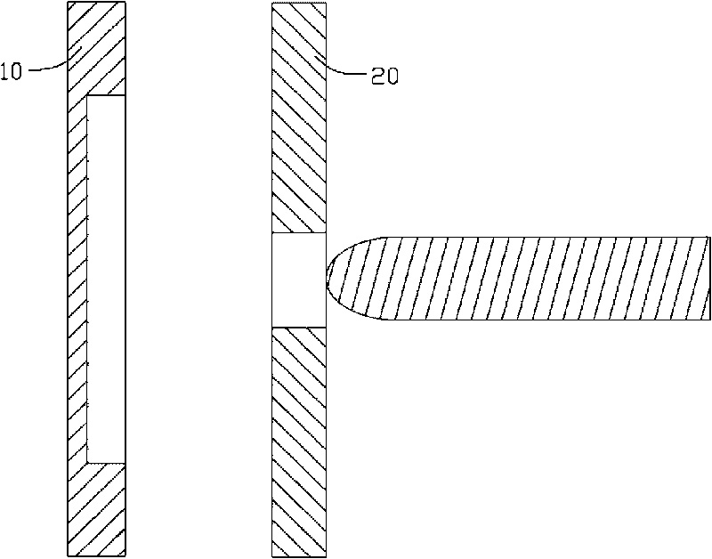
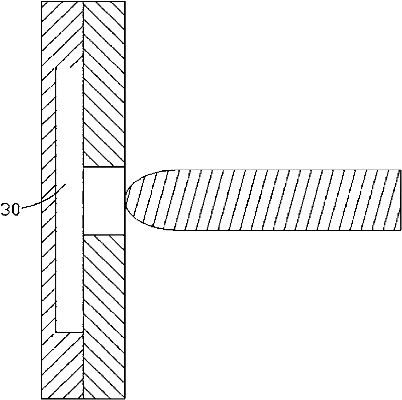
[0019] Such as figure 2 As shown, the injection equipment for manufacturing the light guide plate by injection molding includes a movable mold 10 and a fixed mold 20 . During operation, the fixed mold 20 is relatively fixed, while the movabl...


PUM

PropertyMeasurementUnit
thicknessaaaaaaaaaa
thicknessaaaaaaaaaa
thicknessaaaaaaaaaa

Abstract

The invention relates to an injection molding method for manufacturing a light panel, which is realized in a way that: the light panel is molded by injection under the injection pressure of 2000-4000 kilogram force / square centimeter at the injection speed of 600-1000 millimeter / second. The method molds the light panel under high injection pressure at high injection speed, the high injection speed by injection and high injection speed and pressure can enhance the dimensional accuracy of the product, and thus, the method can manufacture a product with small thickness.

Description

technical field [0001] The invention relates to a method for manufacturing a light guide plate, in particular to a method for manufacturing a thin light guide plate by injection molding. Background technique [0002] At present, the more mature technology of manufacturing light guide plate is to use injection molding (Injection Molding) machine to melt the light guide plate material and push it into the mold cavity of the injection molding machine, maintain the pressure of the mold cavity and cool the light guide plate material, and then mold the product take out. [0003] However, the injection speed and injection pressure of the traditional injection molding machine are relatively low, and the thickness of the molded light guide plate is relatively thick, which makes the backlight module using the light guide plate large in size and high in quality, which is not suitable for light and thin products. Contents of the invention [0004] In view of this, it is necessary to ...

Claims


Application Information

Patent Timeline
Patent Type & Authority Applications(China)
IPC IPC(8): B29C45/76B29C45/77B29C45/66B29C45/26B29L11/00
CPCB29C45/77B29C45/661B29D11/00663B29C45/7653
Inventor 陈杰良
Owner HONG FU JIN PRECISION IND (SHENZHEN) CO LTD
Learn More