
Heat-writing system

A technology of writing head and heater, applied in power transmission device, printing, transfer materials, etc., can solve the problems of slow formation rate, residual bubbles in line traces, unstable laser heat source, etc., and achieve good quality, stable heat source, speed quick effect

Active Publication Date: 2010-06-09
IND TECH RES INST
View PDF1 Cites 1 Cited by
  • Summary
  • Abstract
  • Description
  • Claims
  • Application Information

AI Technical Summary

Problems solved by technology

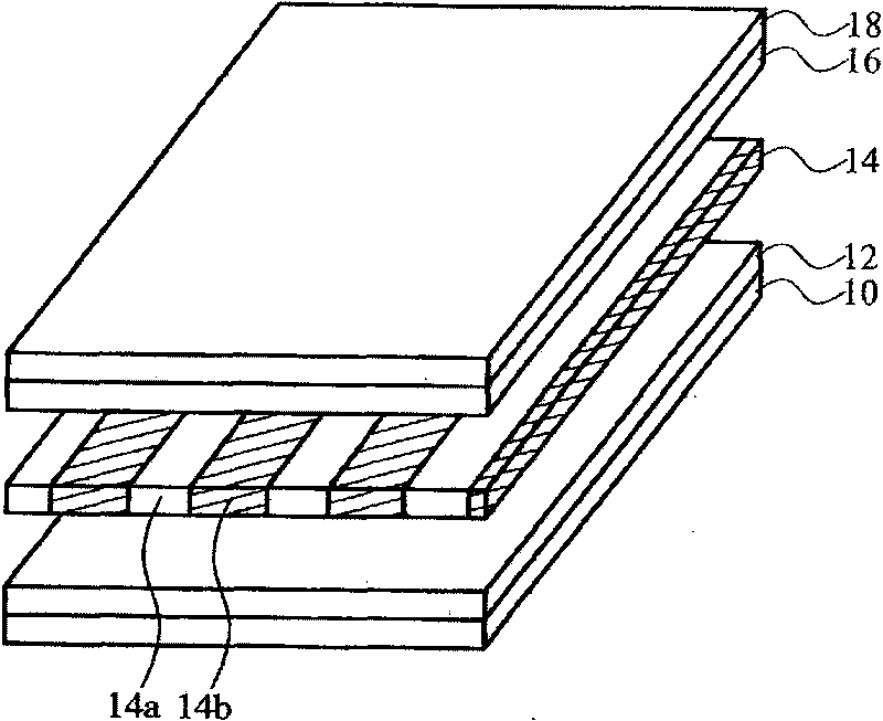
The oblique area 14b of the traditional micro-phase retardation plate 14 is formed by laser scanning multiple lines sequentially, so the formation rate is slow and the laser heat source is unstable. What's more, it leads to traces of lines and residual bubbles

Method used


Image

  • Heat-writing system
  • Heat-writing system
  • Heat-writing system

Examples


Embodiment Construction

[0056] In the following, examples of various embodiments and accompanying drawings are used as a reference basis of the present invention. In the drawings or descriptions in the specification, the same reference numerals are used for similar or identical parts. And in the drawings, the shapes or thicknesses of the embodiments may be enlarged, and marked for simplicity or convenience. Furthermore, parts of each component in the drawings will be described separately. It is worth noting that the components not shown or described in the figure are forms known to those skilled in the art. In addition, specific The examples are only for revealing specific methods used in the present invention, and are not intended to limit the present invention.

[0057] The invention can apply thermal writing technology to the technical fields of large-size soft board and large-size display. The thermal writing technology of each embodiment of the present invention utilizes a thermal writing syst...


PUM


Abstract

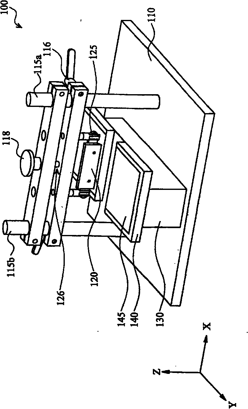
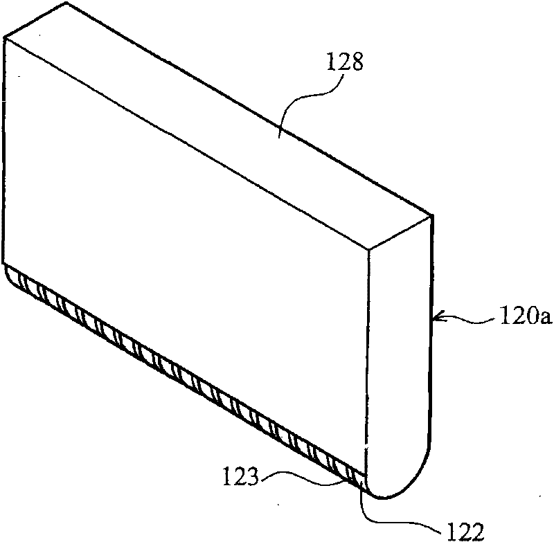
The invention relates to a heat-writing system, comprising a heat-writing head module configured with at least one heater, an elasticity adjusting device for adjusting the flatness of the heat-writing head module, and a rotating control device for controlling the heat-writing head module to rotate a certain angle.

Description

technical field [0001] The present invention relates to a thermal writing system (Systems for thermal patterning), in particular to a thermal writing system for patterning. Background technique [0002] The display panel continues to develop toward larger size and flexibility. In order to achieve rapid and precise manufacturing effects, the manufacturing methods include yellow light development process, laser process, inkjet printing process and thermal printhead printing process. [0003] The traditional yellow light development process is a mature semiconductor mainstream technology, and its process is complex and the cost of automated production is high. Furthermore, CO 2 Laser technology is also currently the actual technology used. However, it must consist of several patterns. There are easy traces between each pattern, and the production speed is slow. The laser heat source is unstable and the quality is not easy to control. On the other hand, the manufacturing cost...

Claims


Application Information

Patent Timeline
Patent Type & Authority Applications(China)
IPC IPC(8): B41J2/32B41J2/335B41J25/316B41J25/312
Inventor 陈英棋蔡朝旭
Owner IND TECH RES INST
Learn More