Drill-following reamer

A reamer and drilling-while-drilling technology, which is applied to drill bits, drilling equipment, earth-moving drilling and mining, etc., can solve the problems of small blade flare angle, large wellbore enlargement rate, and inability to reach it.

Inactive Publication Date: 2010-06-09
SHENGLI PETROLEUM ADMINISTRATION BUREAU DRILLING TECH ACAD SINOPEC
View PDF0 Cites 34 Cited by
  • Summary
  • Abstract
  • Description
  • Claims
  • Application Information

AI Technical Summary

Problems solved by technology

However, due to the design of the piston and the blades, the angle of t...

Method used


Image

  • Drill-following reamer
  • Drill-following reamer

Examples


Embodiment Construction

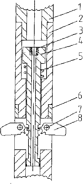
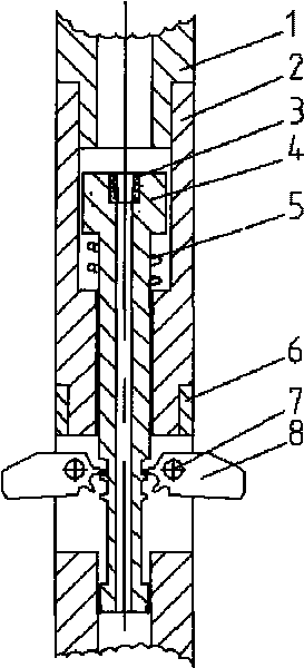
[0008] The present invention will be further described now in conjunction with the accompanying drawings of the description.

[0009] When the present invention is used for reaming while drilling, the upper joint 1 is connected to the drilling tool, the threaded thread at the bottom of the reamer body is connected to the drill bit, and the upper joint 1, reamer body 2, piston nozzle 3, The tool string that piston 4, compression spring 5, limit block 6, bearing pin 7 and knife wing 8 and drill bit form is sent to the bottom of the well. At the wellhead, the circulation system starts to circulate the pump, and the fluid produces a pressure drop at the piston nozzle 3, which generates a thrust on the large end surface of the piston 4, overcomes the reaction force of the compression spring 5, and makes the piston 4 move downward, due to the gear structure on the blade 8 Engage with the groove on the piston 4, so the blade 8 rotates outwards with the pin shaft 7 as the axis. After ...


PUM


Abstract

A drill-following reamer comprises an upper joint, a reamer body, a piston nozzle, a piston, a compression spring, a blade, a pin shaft and a limit stop. The upper part of the whole set of device is connected with a drilling tool through the upper joint, while the lower part is connected with a drill bit through a screw thread. During drill-following reaming operation, the liquid piston nozzle pumped on the ground produces pressure drop to push the piston to move downwards, a groove on the piston pushes a gear structure on the blade to rotate the blade outwards by using the pin shaft as the center when the piston moves downwards till the blade is limited by the limit stop, and then the blade is expanded to reach the maximum outside diameter to start the drill-following reaming operation. 78.6 percent of drill hole expansion rate can be achieved by using the drill-following reamer, so the drill hole expansion rate is high; the blade has the mechanical locking function and is not retracted due to the extrusion of the well wall, so the diameter of the reamed drill hole is regular; and because the drilling and the reaming are carried out at the same time, the drilling cost is saved.

Description

technical field [0001] The invention relates to an improvement of a reamer while drilling. Background technique [0002] The principle of the hydraulic eye reamer currently used in China is to generate a thrust on the piston through hydraulic force, to push the piston to move, and then to push the reamer blade to expand outward to complete the reaming operation. However, due to the design of the piston and the blades, the angle of the blades is relatively small, which cannot achieve a large borehole expansion rate. Contents of the invention [0003] The object of the present invention is to provide a reamer while drilling. When using the reamer for reaming operations, the gear structure of the reamer can achieve a larger blade opening angle, thereby achieving a larger borehole expansion rate. . [0004] In order to solve the above problems, a reamer while drilling includes an upper joint, a reamer body, a piston nozzle, a piston, a compression spring, a blade, a pin shaf...

Claims


Application Information

Patent Timeline
IPC IPC(8): E21B10/32
Inventor 张俊杰吴仲华许俊良聂云飞朱杰然于波王朝平
Owner SHENGLI PETROLEUM ADMINISTRATION BUREAU DRILLING TECH ACAD SINOPEC
Why Eureka
Try Eureka