
Backlight module and display device using same

A technology for a backlight module and a display device, which is applied to lighting devices, fixed lighting devices, components of lighting devices, etc., can solve the problems of burning brightness, short circuit and deformation of light-emitting diodes 130, avoid abnormal display, and improve assembly yield. , the effect of preventing short circuit

Inactive Publication Date: 2010-06-09
AU OPTRONICS CORP
View PDF0 Cites 5 Cited by
  • Summary
  • Abstract
  • Description
  • Claims
  • Application Information

AI Technical Summary

Problems solved by technology

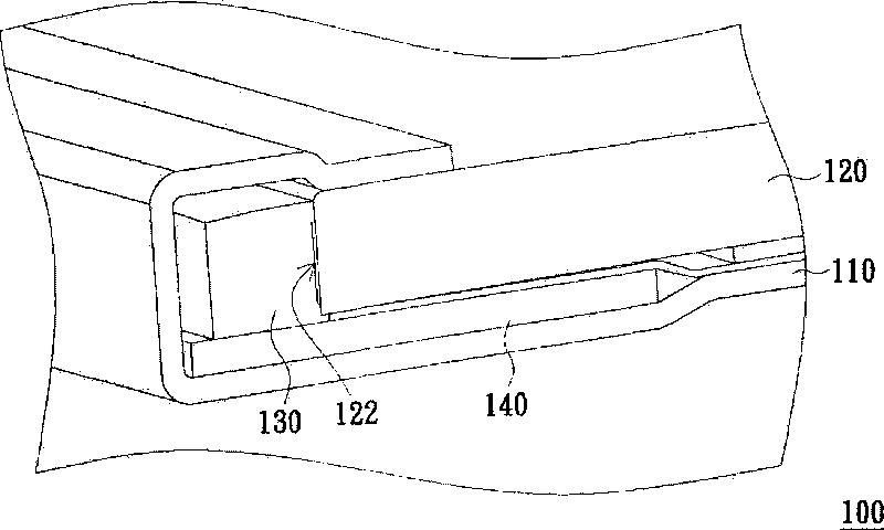
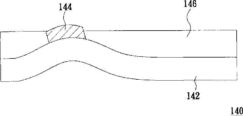
However, if the plastic substrate 142 is accidentally deformed due to external impact or other human factors before the formation of the insulating protection layer 146, the circuit structure 144 disposed thereon will also be deformed accordingly, resulting in the subsequent formation of the insulating protection layer 146. The circuit structure 144 cannot be completely covered, causing a part of the circuit structure 144 to be exposed outside the insulating protection layer 146
[0005] Please refer again figure 1 , when the circuit board 140 is arranged on the metal frame 110, the circuit structure 144 is likely to be short-circuited due to the contact between the exposed part and the metal frame 110, causing the light-emitting diode 130 to be burned or the brightness to be reduced, thereby affecting the light output uniformity of the backlight module 100 Spend

Method used


Image

  • Backlight module and display device using same
  • Backlight module and display device using same
  • Backlight module and display device using same

Examples


Embodiment Construction

[0061] In order to make the above and other objects, features and advantages of the present invention more comprehensible, preferred embodiments are specifically cited below and described in detail with accompanying drawings.

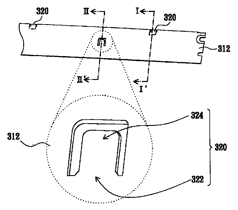
[0062] Figure 3A It is a schematic diagram of the back of the backlight module in an embodiment of the present invention, Figure 3B for Figure 3A The cross-sectional schematic diagram of the backlight module along the line I-I', Figure 3C then Figure 3A The schematic cross-sectional view of the backlight module along the line II-II'. Please refer to Figure 3A and Figure 3B, the backlight module 300 includes a frame 310 , a plurality of protrusion structures 320 , a light guide plate 330 , a circuit board 340 and a plurality of light emitting diodes 350 . The frame 310 is made of metal material, for example, and it includes a bottom 312, a connection portion 314 and an extension portion 316, wherein the bottom 312 has an upper surface 311, a...


PUM


Abstract

The invention discloses a display device which comprises a display panel and a backlight module, wherein the backlight module comprises a frame, a plurality of convex structures, a light guide plate, a circuit board and a plurality of light-emitting diodes; the circuit board is provided with a plurality of line exhausting area and a line configuring area and comprises a line structure which is configured in the line configuring area; the convex structures are configured on the upper surface of the bottom of the frame and are in contact with the line exhausting area of the circuit board to support the circuit board, and the line configuring area is suspended above the bottom of the frame; the light guide plate is configured on the bottom of the frame and provided with a projecting surface and an incidence surface; and the light-emitting diodes are configured on the circuit board, electrically connected with the line structure and positioned beside the incidence surface of the light guide plate and are suitable for emitting light rays inside the light guide plate. The invention can improve the assembly yield of the backlight module to prevent short circuit caused by that the carelessly exposed line structure is in contact with the frame, and solves the problem of abnormal display of the display device by the damage of the light-emitting diodes due to the short circuit of the line structure.

Description

technical field [0001] The invention relates to a backlight module, in particular to a backlight module with high assembly yield and a display device using the backlight module. Background technique [0002] The backlight module is used to provide a display light source required by a liquid crystal display panel (LCD panel). The backlight module can be divided into direct type and side type according to the light input method, and the side type backlight module usually uses a light guide plate (LGP) to convert the light provided by the light source into a surface light source. On the other hand, due to the characteristics of high brightness and small size, light emitting diodes (LEDs) have been gradually used in backlight modules, so that liquid crystal displays can be further developed towards the goal of lightness, thinness and high brightness. develop. [0003] figure 1 It is a schematic cross-sectional view of an existing side-illuminated backlight module. Please ref...

Claims


Application Information

Patent Timeline
Patent Type & Authority Applications(China)
IPC IPC(8): F21S8/00F21V17/10F21V8/00F21V23/00F21V19/00G02F1/13357G02F1/1333F21Y101/02
Inventor 陈誉友潘治良
Owner AU OPTRONICS CORP
Learn More