Back light module
A backlight module and substrate technology, applied in optics, light source fixation, nonlinear optics, etc., can solve the problems of reducing area, loosening of support frame and lamp tube, and reduction of glue viscosity, so as to achieve easy assembly, increase The effect of backlight uniformity, manufacturing cost reduction
- Summary
- Abstract
- Description
- Claims
- Application Information
AI Technical Summary
Problems solved by technology
Method used
Image

Examples
no. 1 example
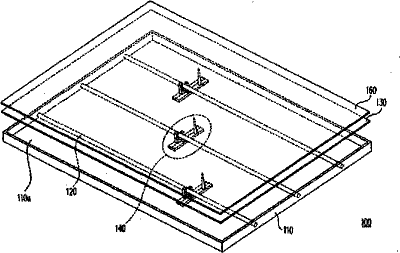
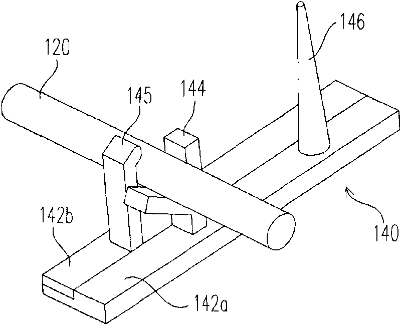
[0044] Figure 2A It is a schematic diagram of the supporting structure of the first embodiment of the present invention. Please refer to Figure 2A , in the first embodiment, each support structure 140 includes a first base material 142 a , at least one lamp tube supporting portion 144 , a second base material 142 b , at least one lamp tube fixing portion 145 and at least one thimble 146 . The lamp support portion 144 is disposed on the first base material 142a, and the second base material 142b is adjacent to the first base material 142a. The light tube fixing portion 145 is disposed on the second base material 142b, wherein each light tube supporting portion 144 is provided corresponding to one light tube fixing portion 145 for supporting and fixing one of the light tubes 120 . The thimble 146 is disposed on the first substrate 142a or the second substrate 142b (in FIG. 2A, the thimble 146 is disposed on the first substrate 142a as an example for illustration), and the th...
no. 2 example
[0050] Figure 3A is a schematic diagram of the support structure fixed to the bottom plate in the second embodiment of the present invention, Figure 3B for Figure 3A An exploded schematic of the support structure and baseplate. Please also refer to Figure 3A and Figure 3B , this embodiment is similar to the first embodiment, the difference is: in this embodiment, each supporting structure 140 further includes at least one fixing member 147, which is arranged on the first substrate 142a and the second substrate 142b between. The fixing member 147 includes a protruding portion 147a and a recessed portion 147b, the protruding portion 147a is disposed on the side surface of the first base material 142a, and the recessed portion 147b is disposed on the side surface of the second base material 142b.
[0051] Please also refer to Figure 3A and 3B , when assembling the lamp tube 120, put the lamp tube 120 into the lamp tube support part 144 first, and then insert the side...
no. 3 example
[0055] Figure 4A It is a schematic diagram of the support structure fixed on the bottom plate according to the third embodiment of the present invention. Please refer to Figure 4A , this embodiment is similar to the first embodiment, the difference is that in this embodiment, the bottom plate 110a further includes at least one first opening 112a and at least one second opening 112b, and each supporting structure 140 further includes at least A fastening component 148 and at least one moving piece 149 . The fastener 148 is disposed on the bottom of one of the first substrate 142a and the second substrate 142b (Figure 4A is an example of the fastener 148 being disposed on the first substrate 142a for illustration), and from the bottom plate The first opening 112a of 110a protrudes from the bottom plate 110a and is buckled on the bottom plate 110a. The moving piece 149 is arranged on the other bottom of the first base material 142a and the second base material 142b (figure 4...
PUM
 Abstract
Description
Claims
Application Information
 - R&D Engineer
- R&D Manager
- IP Professional
- Industry Leading Data Capabilities
- Powerful AI technology
- Patent DNA Extraction
Browse by: Latest US Patents, China's latest patents, Technical Efficacy Thesaurus, Application Domain, Technology Topic.
© 2024 PatSnap. All rights reserved.Legal|Privacy policy|Modern Slavery Act Transparency Statement|Sitemap