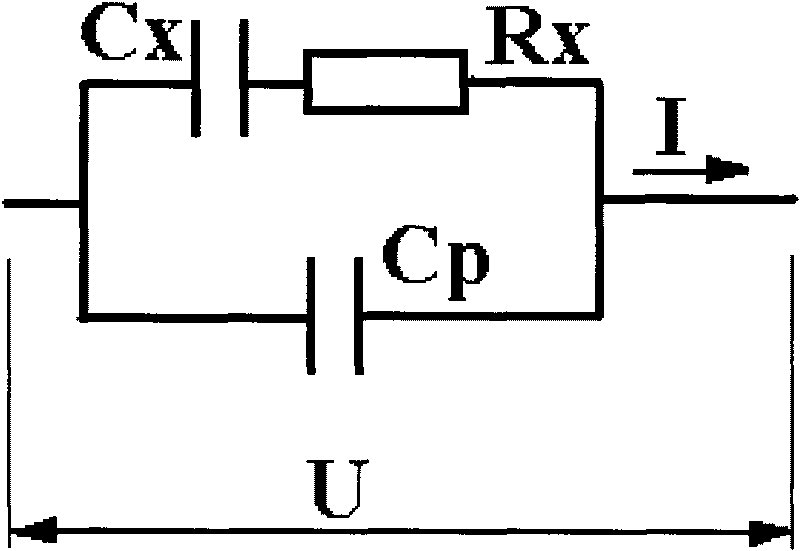
Method for measuring electrical conductivity of solution

A measurement method and conductivity technology, which is applied in the direction of material resistance, etc., can solve the problems of small influence of electrode polarization factors in the solution between electrodes, inconvenience, large measurement errors, etc.

Inactive Publication Date: 2010-06-09
FUJIAN NORMAL UNIV
View PDF6 Cites 28 Cited by
  • Summary
  • Abstract
  • Description
  • Claims
  • Application Information

AI Technical Summary

Problems solved by technology

The mathematical calculation formula proposed by this method is derived based on the conductivity cell model ignoring the influence of electrode polarization, and is only suitable for low conductivity measurement occasions; for high conductivity solutions, the solution resistance is small, and the equivalent capacitance of electrode polarization is affected Relatively strong, in this case the measurement error of the method is large
[0009] The document with the Chinese patent application number CN 200610024967.9 discloses a measurement method, which measures the solution resistance or conductance at two time points separated by 1/4 cycle within the half cycle of the excitation signal. When the difference between the measured values ​​does not exceed the set limit , the measured value is considered to be valid, and when it exceeds the set limit, an alarm will be issued to remind you to replace an electrode with a larger electrode constant; The influence is relatively smaller; the disadvantage of this method is that increasing the electrode constant will reduce the influence of...

Method used


Image

  • Method for measuring electrical conductivity of solution
  • Method for measuring electrical conductivity of solution
  • Method for measuring electrical conductivity of solution

Examples


Embodiment 1

[0060] The AD converter adopts a general-purpose dual-channel high-speed A / D converter, and performs high-speed equal interval sampling on the excitation voltage and the response current at the same time. The method of calculating U, I, and P is to integrate the sampling values ​​within an integer number of signal periods according to the standard Define the formula to proceed, the formula is as follows:

[0061] U = 1 T ∫ 0 T u 2 dt , I = 1 T ∫ 0 T i 2 dt , P = 1 T ∫ 0 T ( u...

Embodiment 2

[0064] The AD converter uses a dedicated electrical parameter measurement chip with a voltage input channel and a current input channel as the A / D, and the calculation of U, I, and P is completed by the dedicated electrical parameter measurement chip, as long as the A / D conversion and reading are started according to the instructions of the chip. Get the conversion result. This embodiment can reduce the calculation workload of the main control chip, and can also make full use of the special chip's advantages in measurement and calculation, such as good repeatability, strong anti-interference ability, and high calculation accuracy.


PUM


Abstract

The invention discloses a method for measuring the electrical conductivity of solution, comprising the following steps of: exciting electrodes by adopting a sinusoidal signal with stable voltage amplitude and fixed frequency; carrying out two-channel high-speed A/D transformation on an excitation voltage signal and a current signal of electrode response at the same time; computing voltage effective value U, current effective value I and active power P; dividing the current effective value I by the voltage effective value U to obtain an apparent resistance m, computing a power factor cosine theta and tangent absolute value n of a power factor angle theta, and computing the resistance value Rx between the electrodes by utilizing the following formula, wherein the omega in the formula is angular frequency of the excitation signal and Cp expresses the sum of distributed capacitances between the electrodes and electrode leads; and obtaining the electrical conductivity by utilizing the formula G=K/Rx, wherein the K is an electrode constant. By adopting the invention, adverse effects of electrode polarization, electrode interelectrode and electrode lead distributed capacitances to the measurement of electrical conductivity of the solution can be completely eliminated, and the electrical conductivity of the solution can accurately measured.

Description

technical field [0001] The present invention relates to the measurement method of solution conductivity or resistivity, especially relates to the measurement method that can completely eliminate electrode polarization and the distributed capacitance between electrode pole, electrode lead wire to solution conductivity or resistivity measurement method, is accurate conductivity or Resistivity measurement method. Background technique [0002] The basic measurement method of the conductivity of the solution is to measure the voltage U applied to the two ends of the electrode placed in the solution and the current I flowing through the electrode, and calculate the resistance between the electrodes R=U / I, calculated by G=K / R The conductivity of the solution, where K is the cell constant. However, the electrodes placed in the solution will be polarized after being energized, so that the measured voltage U is not actually the voltage at both ends of the solution itself, but the vol...

Claims


Application Information

Patent Timeline
IPC IPC(8): G01N27/06
Inventor 廖晓东洪亲蔡坚勇
Owner FUJIAN NORMAL UNIV
Why Eureka
Try Eureka