Drive circuit of light source

A light source driving circuit and current value technology, applied in the direction of instruments, static indicators, etc., can solve the problems of reducing the service life of the backlight module and increasing power consumption, and achieve the effects of reducing system cost, increasing maximum brightness, and increasing power consumption

Active Publication Date: 2010-06-09
苏州盛泽科技创业园发展有限公司
View PDF0 Cites 5 Cited by
  • Summary
  • Abstract
  • Description
  • Claims
  • Application Information

AI Technical Summary

Problems solved by technology

[0010] However, when the known technology intends to increase the maximum brightness of the backlight source, the known light source driving circuit 100 must increase the standard current value I spec , to thereby increase the drive pulse PU 11 ~PU 1n voltage level
At this time, the power consumption of the known light source driving circuit 100 will be relatively increased
In addition, the junction temperature of the light-emitting diode will also increase with the standard current value I spec Improvement and increase, thereby reducing the service life of the backlight module

Method used


Image

  • Drive circuit of light source
  • Drive circuit of light source
  • Drive circuit of light source

Examples


Embodiment Construction

[0028] Before describing the spirit of the present invention with the embodiments, it is first assumed that the light source driving circuit listed in each embodiment is applicable to a backlight module. In addition, the light source driving circuit described in each embodiment is further used to drive a plurality of light-emitting components (not shown) arranged in the backlight module, so that the light-emitting components generate light. Wherein, the light-emitting components may respectively be composed of a light-emitting diode. However, the above assumptions are not intended to limit the present invention, and those skilled in the art can also change the application type of the light source driving circuit according to the spirit of the present invention.

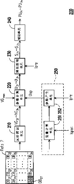
[0029] Figure 2A It is a circuit structure diagram of a light source driving circuit according to an embodiment of the present invention. refer to Figure 2A The light source driving circuit 200 includes a graysca...


PUM


Abstract

A drive circuit of a light source comprises a gray scale recognition unit, a parameter optimization module, a parameter calculation unit, a light-regulation control unit ad a drive unit. The gray scale recognition unit is used for capturing the maximal gray scale values individually corresponding to a plurality of data blocks in image data. The parameter optimization module generates an optimized period value according to the ratio of a standard current value to a specific current value. The parameter calculation unit obtains a specific value according to the optimized period value and the maximal gray scale values of the image and multiplies the maximal gray scale values of the data blocks by the specific value respectively to obtain a plurality of working period values. The light-regulation control unit generates a plurality of light-regulation control signals according to the working period values and the specific current value. Thus, the drive unit generates a plurality of drive pulse waves according to the light-regulation control signals.

Description

technical field [0001] The present invention relates to a light source driving circuit, and in particular to a light source driving circuit which utilizes parameter optimization to reduce power consumption. Background technique [0002] In recent years, liquid crystal displays (LCDs) have been widely used in various electronic products requiring display devices due to their advantages of light and thin size and low power consumption. Liquid crystal displays use the optical activity and photoelectric properties of liquid crystal materials to display images. However, since the liquid crystal material itself does not have the function of emitting light, the liquid crystal display must be equipped with a backlight module to provide the light source required for displaying images. [0003] In the process of providing the light source, the backlight module utilizes a light source driving circuit to drive the light-emitting component, so that the light-emitting component generates...

Claims


Application Information

Patent Timeline
Patent Type & Authority Applications(China)
IPC IPC(8): G09G3/20G09G3/36
Inventor 林琦修黄常新魏兆威
Owner 苏州盛泽科技创业园发展有限公司
Why Eureka
Try Eureka