
Heat transfer sheet and radiator structure

A technology of heat transfer sheet and structure, which is applied in the direction of heat transfer modification, electric solid devices, semiconductor devices, etc., which can solve the problems of excessive cooling of the exothermic object and the inability of the exothermic object to fully exert its performance, so as to prevent excessive Effects of Cooling and Overheating

Inactive Publication Date: 2010-06-09
SUMITOMO BAKELITE CO LTD +2
View PDF1 Cites 4 Cited by
  • Summary
  • Abstract
  • Description
  • Claims
  • Application Information

AI Technical Summary

Problems solved by technology

[0004] However, since the thin plate described in Patent Document 1 maintains a constant thermal conductivity in the thickness direction regardless of temperature changes, when the above-mentioned exothermic object is used in an environment with an extremely low temperature, the exothermic object will be destroyed. Excessive cooling, depending on the type of exothermic object, the exothermic object may not be able to fully exhibit its performance

Method used


Image

  • Heat transfer sheet and radiator structure
  • Heat transfer sheet and radiator structure
  • Heat transfer sheet and radiator structure

Examples


Embodiment Construction

[0051] Below, based on Figure 1 to Figure 5 Embodiments of the heat transfer sheet of the present invention will be described in detail.

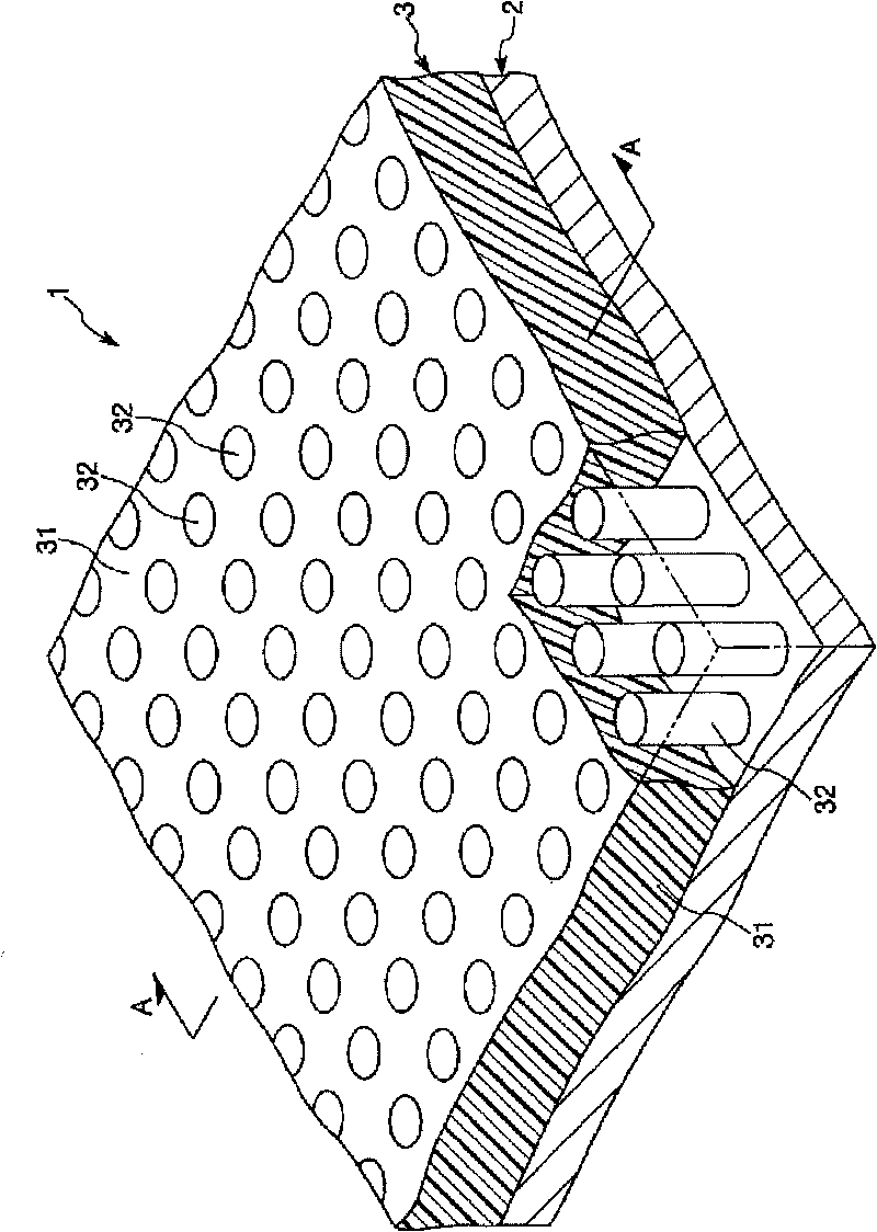
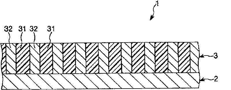
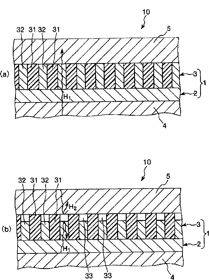
[0052] figure 1 is a perspective view showing a schematic structure of a preferred embodiment of the heat transfer sheet of the present invention, figure 2 yes figure 1 Middle A-A line sectional view, image 3 is for illustration figure 1 The diagram showing the action of the heat transfer fins, Figure 4 It is a figure for explaining the specific example of the exothermic structure of this invention, Figure 5 yes means Figure 4 A perspective view of the main part of the exothermic structure shown.

[0053] Such as figure 1 and figure 2 As shown, and as described later, the heat transfer sheet 1 of the present invention is used between a heat radiation target object and a counterpart object that must be radiated heat, and is used for performing the heat radiation target object and the counterpart body. Heat transfer fins for he...


PUM

PropertyMeasurementUnit
particle diameteraaaaaaaaaa
weight-average molecular weightaaaaaaaaaa

Abstract

A heat transfer sheet comprising a heat transfer layer having a first area and, provided in a position different in planar view from the first area, a second area capable of expansion and contraction at a ratio greater than in the first area along the thickness direction in accordance with temperature changes, wherein in use conditions, when the temperature of the heat transfer layer is a given value or below, a gap is formed between the second part and an opposite party to thereby lower the heat conduction between a radiator object and the opposite party, while when the temperature of the heat transfer layer is not lower than the given value, substantially no gap is laid therebetween to thereby increase the heat conduction between the radiator object and the opposite party.

Description

technical field [0001] The invention relates to a heat transfer sheet used between a heat release object as an object to be released heat and a corresponding counterpart to conduct heat transfer between the heat release object and the counterpart and its use The heat dissipation structure of the heat transfer sheet. Background technique [0002] Conventionally, thin plates with high thermal conductivity (e.g., , refer to Patent Document 1: JP Unexamined Patent Publication No. 2006-278476). [0003] As described in Patent Document 1, for example, the sheet is composed of a resin composition containing a resin and a thermally conductive filler. By interposing the thin plate between the heat radiation fin and the above-mentioned heat radiation target object, heat transfer from the heat radiation target object to the heat radiation fin can be effectively performed, and excessive temperature rise of the target object can be prevented. [0004] However, since the thin plate des...

Claims


Application Information

Patent Timeline
Patent Type & Authority Applications(China)
IPC IPC(8): H01L23/36C09K5/08H01L23/373H05K7/20
CPCH01L23/3733H01L2924/0002H01L23/433H01L23/3737H01L23/34C09K5/14F28F3/02F28F2013/006Y10T29/49352H01L2924/00B23P15/26
Inventor 村田崇中村好志高桥泉荘肇博清水一基新居良英伊藤真一郎川口均杉野光生
Owner SUMITOMO BAKELITE CO LTD
Learn More