
Device for press-fitting crank case bearing

A crankcase and bearing technology, applied in the field of fixtures, can solve problems such as box crushing, unfavorable batch production, and affecting work efficiency, so as to avoid crushing or crushing, improve assembly cleanliness, and improve assembly efficiency.

Inactive Publication Date: 2011-06-29
力帆科技(集团)股份有限公司
View PDF0 Cites 0 Cited by
  • Summary
  • Abstract
  • Description
  • Claims
  • Application Information

AI Technical Summary

Problems solved by technology

[0003] 1. Only one bearing can be press-fitted at a time, and the same box needs to be press-fitted several times to complete the assembly of all bearings. The assembly efficiency is low, which is not conducive to mass production
[0004] 2. During the press-fitting process, it is necessary to hold the bearing with hands. Not only is the operation cumbersome, the labor intensity of the workers is high, and it is easy to crush the hands of the workers, causing frequent safety accidents
[0005] 3. The box body is not positioned on the worktable, and the alignment between the box body bearing chamber and the column tooling is carried out based on the worker's feeling and experience. The accuracy is poor, and it is easy to cause the press fit to be in place, or the bearing pressure to be skewed. It not only affects the work efficiency, but also makes it difficult to guarantee the quality of the assembly. In severe cases, the cabinet may even be crushed or damaged, causing the cabinet to be scrapped.
[0006] 4. Since the coordinates and depth of each bearing chamber of the box are different, the traditional method can only press the bearing into a specific bearing chamber, and cannot detect whether the coordinates and depth of the bearing chamber are qualified
[0007] 5. Since the precise positioning between the columnar tooling and the bearing chamber is difficult, the assembly clearance of the bearing is not easy to control, and the assembly cleanliness of the bearing is poor, which will affect the performance of the complete engine and shorten the service life of the bearing and the engine

Method used


Image

  • Device for press-fitting crank case bearing
  • Device for press-fitting crank case bearing
  • Device for press-fitting crank case bearing

Examples

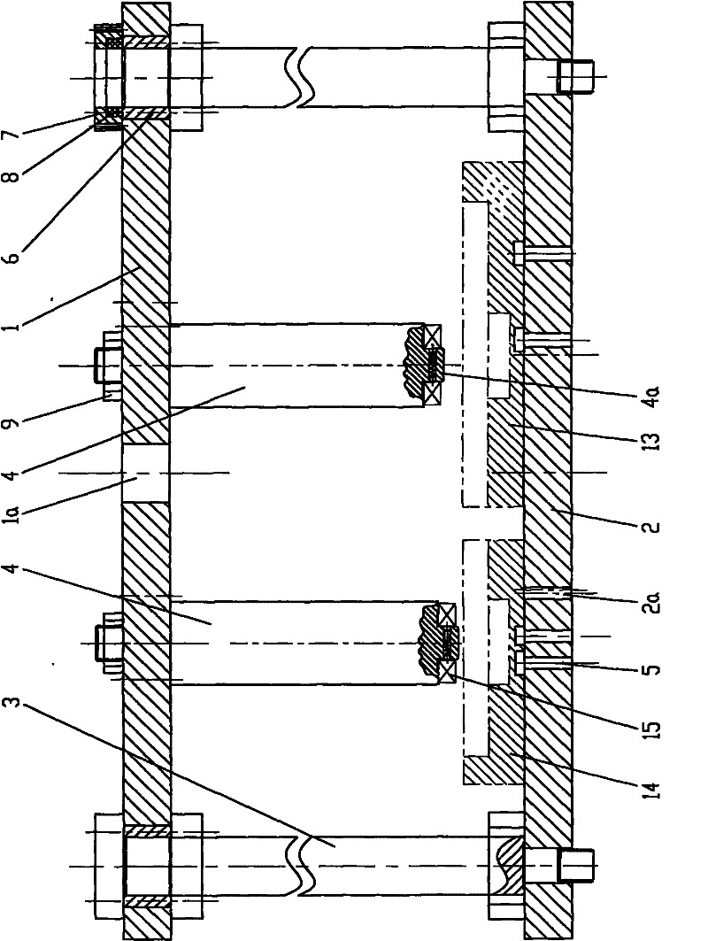
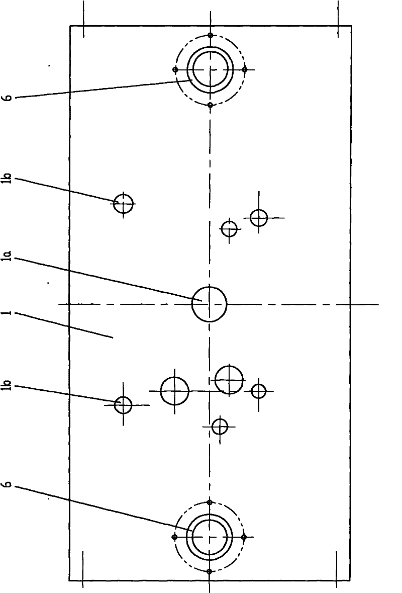
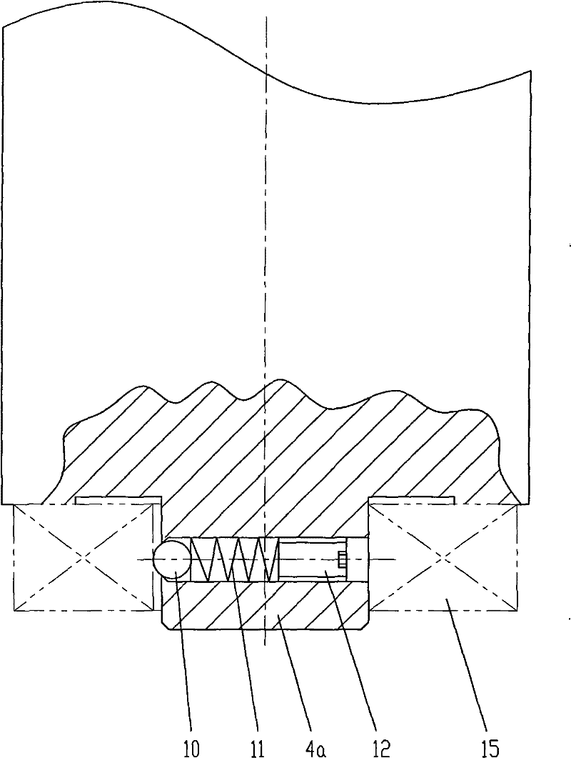

Embodiment Construction

[0028] Below in conjunction with accompanying drawing and embodiment the present invention will be further described:

[0029] like figure 1 , figure 2 As shown, the present invention consists of an upper template 1, a lower template 2, a guide rod 3, a pressure head shaft 4, a positioning pin 5, a copper sleeve 6, an end cover 7, an oil seal 8, a nut 9, a steel ball 10, a spring 11 and a tight top Parts such as screw 12 are formed, and wherein upper and lower formwork 1,2 are the rectangular flat plates that are arranged horizontally, and upper formwork 1 is positioned at the direct top of lower formwork 2. A through hole 1a connected to the press is opened in the center of the upper template 1, and a set of through holes 1b are respectively arranged on the left and right sides of the through hole 1a, and each set of through holes 1b corresponds to a set of indenter shafts 4, namely The indenter shaft 4 is perpendicular to the upper template 1 , and the upper end of the in...


PUM


Abstract

The invention discloses a device for press-fitting crankcase bearing. An upper die plate is arranged above a lower die plate in parallel, the left and right ends of the upper and lower die plates are connected by a guide rod, the upper die plate can move up and down along the guide rod; the center of the upper die plate is opened with a through hole connected with a press machine, the left and right sides of the through hole are respectively provided with a group of pressure head shafts, each group of pressure head shafts are distributed by the position of bearing chamber in the crankcase body, the pressure head shaft is vertical to the upper die plate, the upper end of the pressure head shaft is fixedly connected with the upper die plate, the lower end of the pressure head shaft points at the board of the lower die plate, and the center at the lower end of the pressure head shaft is provided with a round locating boss. The invention can complete the assembly of the whole bearings of two case bodies by once press-fitting, not only operation is simple and labour intensity of workers is reduced, but also assembly efficiency is greatly improved, assembly quality is ensured, and the case body is avoided to be crushed.

Description

technical field [0001] The invention belongs to the technical field of fixtures, and in particular relates to press-fitting fixtures for crankcase bearings. Background technique [0002] A plurality of bearing chambers are arranged in the left and right casings of the crankcase of the motorcycle engine, and the bearing chambers are press-fitted with bearings for supporting the transmission shaft. At present, the method of press-fitting the bearings in the left and right cases of the crankcase is to use columnar tooling and provide power through the press, that is, place the left or right case on the work table to make a certain bearing chamber in the case Facing the pressure head of the press, then place the bearing on the lower end of the column tooling, and hold the bearing with your hand to prevent the bearing from falling, then turn on the press, press the pressure head of the press down, and the press pushes the column through the pressure head The tooling moves down, ...

Claims


Application Information

Patent Timeline
Patent Type & Authority Patents(China)
IPC IPC(8): B23P19/02
Inventor 何成念周文全王胜华谯平钟涛
Owner 力帆科技(集团)股份有限公司
Learn More