Take-up winding facility

A kind of equipment and spinning technology, which can be used in the production of complete sets of equipment for man-made threads, filament generation, textiles and papermaking, etc. It can solve the problems of complex equipment and achieve the effect of reducing height, improving efficiency and reducing costs.

Active Publication Date: 2010-06-16
TMT MACHINERY INC
View PDF7 Cites 8 Cited by
  • Summary
  • Abstract
  • Description
  • Claims
  • Application Information

AI Technical Summary

Problems solved by technology

Therefore, there is no need to extend the distance from the winder to the preceding wire feed roll,

Method used


Image

  • Take-up winding facility
  • Take-up winding facility
  • Take-up winding facility

Examples


Embodiment Construction

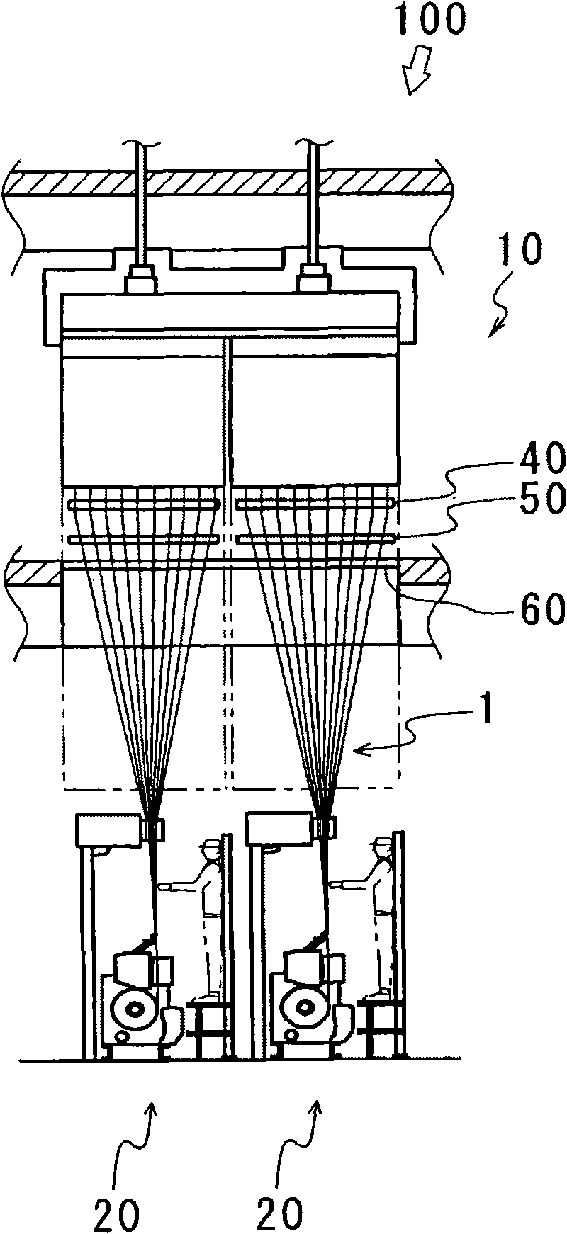
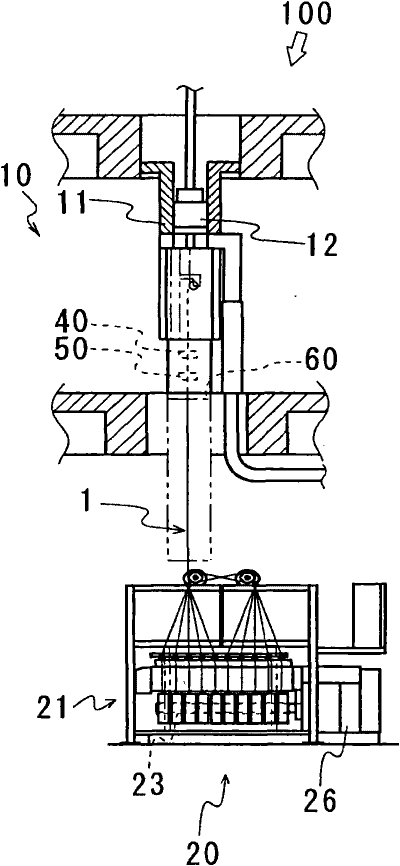
[0053] First, the overall structure of the spinning and winding apparatus 100 of the present invention will be described with reference to FIG. 1 . Figure 1A is a front view of the spin-winding apparatus 100, Figure 1B its side view. In addition, let the action direction of gravity be the up-down direction, let the axial direction of the bobbin holder shaft 23 provided in the winder 21 be the front-rear direction, and let the side of the bobbin holder shaft 23 connected to the drive device 26 be the rear side , and use the other side as the front side. In addition, the direction orthogonal to the vertical direction and the front-rear direction when the winder 21 is viewed from the front side is referred to as the left-right direction.

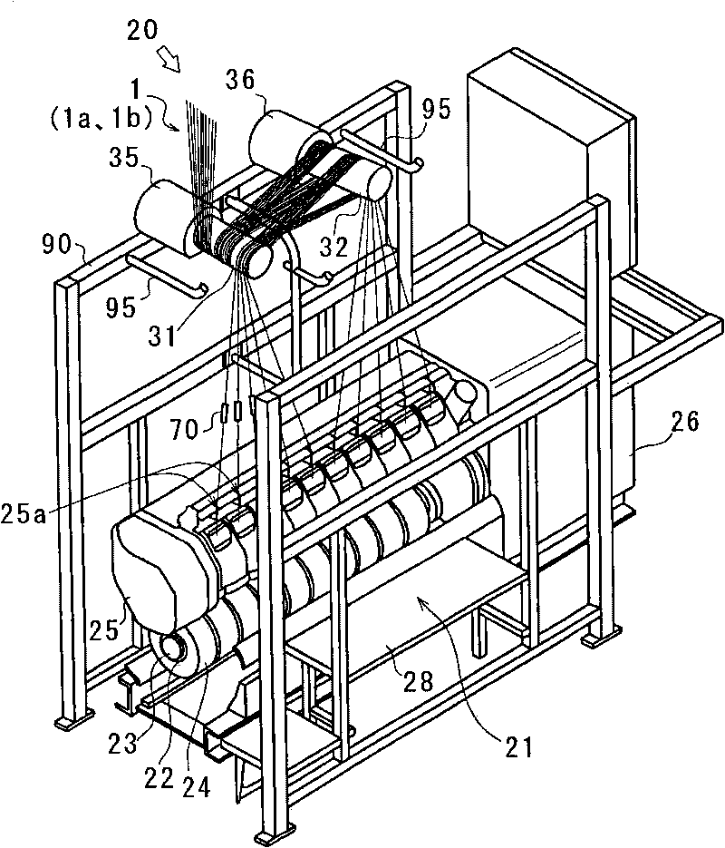
[0054] The spinning and winding apparatus 100 is mainly composed of a spinning machine 10 for spinning a plurality of yarns 1 and a spinning and winding device 20 for winding the yarns 1 spun from the spinning machine 10 .

[0055] The spi...


PUM


Abstract

An object of the present invention is to provide a take-up winding facility having a simple structure and which can be miniaturized. The present invention provides a take-up winding facility 10 feeding a plurality of filament yarns 1 spun out by a spinning machine 10, from above to below to simultaneously wind the plurality of filament yarns 1 around respective plural bobbins 22 installed on a bobbin holder shaft 23 in one take-up winding machine, wherein a plurality of yarn feeding rollers 31, ... are arranged above the take-up winding machine 21, and one of the plurality of yarn feeding rollers 31, ... takes off all of the plurality of filament yarns and winds around the respective bobbins 22 via the said yarn feeding roller and other yarn feeding rollers.

Description

technical field [0001] The present invention relates to a spinning winding device for winding a plurality of yarns spun from a spinning machine by a winding machine through a plurality of rolls. Background technique [0002] The spinning and winding equipment of the prior art adopts such a structure: relative to a winding machine, a wire feeding roller arranged in front of the winding machine is arranged, and all the multiple silk threads spun from the spinning machine are fed from the feeding roller. It is guided to and wound on a plurality of bobbins mounted on one winding machine (refer to Patent Document 1). [0003] And as other examples of the spinning and winding equipment of the prior art, such structure is adopted: two feeding rollers arranged in front of the winding machine are respectively set relative to one winding machine, and the multi-spinning rollers spun out from the spinning machine are The yarns are separately guided from the yarn feed rollers to bobbins...

Claims


Application Information

Patent Timeline
IPC IPC(8): D01D7/00D01D11/00D01D13/00B65H54/02B65H51/005B65H51/12B65H67/08B65H71/00
CPCB65H54/20B65H71/007B65H2701/3132B65H51/015B65H51/12B65H54/2881
Inventor 中川理
Owner TMT MACHINERY INC
Why Eureka
Try Eureka