Method for operating free end spinning machine and free end spinning machine thereof

A free-end, mechanical technology, applied in the field of winding devices for manufacturing cross-winding bobbins, can solve the problems of high price, no use value, and low economy, and achieve the effect of simple application

Active Publication Date: 2010-06-16
SAURER GERMANY GMBH & CO KG
View PDF8 Cites 11 Cited by
  • Summary
  • Abstract
  • Description
  • Claims
  • Application Information

AI Technical Summary

Problems solved by technology

[0007] Such a device is described, for example, in the German patent DE 10 2004 057 825 A1 in connection with an automatic cross-winder for monitoring the filling state of a pneumatic yarn store, which is usually configured as an optical or capacitive sensor device and quite expensive
This means that the use of such a sensor device in open-end rotor spinning machines with 300 and more than 300 positions is not economical and therefore useless

Method used


Image

  • Method for operating free end spinning machine and free end spinning machine thereof
  • Method for operating free end spinning machine and free end spinning machine thereof
  • Method for operating free end spinning machine and free end spinning machine thereof

Examples


Embodiment Construction

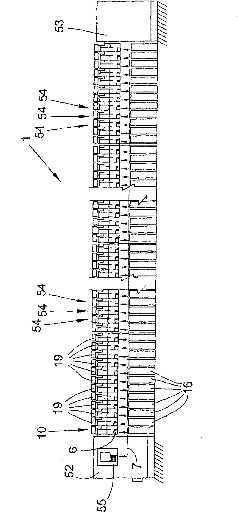
[0022] figure 1 Schematically shows a front view of an open-end rotor spinning machine 1 with so-called end frames 52 , 53 , which are connected to one another as known and therefore not further illustrated by continuous access channels , the access channel is, for example, a negative pressure channel for supplying spinning negative pressure to the spinning device, an electronic channel for a bus system and / or a yarn monitoring device, and a cable channel for supplying power to the station 54. These access channels represent to a certain extent the "backbone" of the textile machine, to which the yarn forming device or the cross-winding device of the rotor spinning machine 1 can be fixed, the yarn forming device or the cross-winding device forming the A plurality of common stations 54 and a leading station 10. At these stations 54 the feed sliver stored in the spinning drum 16 is spun into yarn wound onto the cross-wound package 19 . For example, the negative pressure supply ...


PUM


Abstract

The present invention relates to a method for operating a free end spinning machine and the free end spinning machine with a plurality of stations, wherein, each station is provided with a spinning device and a winding device used for manufacturing cross wounding bobbins. Furthermore a yarn storing device temporarily stores the yarn amount generated because of different accelerations of the spinning device and the winding device in the accelerated operation period of station. According to the invention, at a state of new batch, the tension of yarn in acceleration is measured on at least one station for aiming at various diameters of the cross wounding bobbins, wherein, the tension of yarn is a scale of the filling state of the yarn storing device. acceleration characteristic curves are confirmed for various diameters of the cross wounding bobbin depending on the acceleration speed of the yarn tension regulation winding device according to the regulated speed. Then the acceleration characteristic curves related with the diameters are applied for aiming at the corresponding batches in the acceleration period of the stations.

Description

technical field [0001] The invention relates to a method of operating an open-end spinning machine with a plurality of stations, wherein the stations have a spinning device and a yarn take-off device as well as a winding device for producing cross-wound bobbins, and the yarn The storage device temporarily stores the amount of yarn that occurs during the accelerated operation of the station due to the different acceleration speeds of the spinning device and the winding device. The invention also relates to an open-end spinning machine for carrying out the method. Background technique [0002] In order to store the yarn during acceleration, a pneumatically working yarn accumulator is often used in practice. Such yarn accumulators are known, for example, from German patents DE-AS 2 221 316, DE 101 39 075 A1 or DE 102005 055 717 A1. [0003] In German patent DE-AS 2 221 316 an open-end rotor spinning machine is described, the station of which has an open-end spinning device, a...

Claims


Application Information

Patent Timeline
Patent Type & Authority Applications(China)
IPC IPC(8): D01H4/40D01H4/42D01H13/32B65H59/38
CPCD01H4/44D01H4/50B65H2701/31B65H2513/514B65H51/205B65H2513/512
Inventor 弗兰克·弗伦岑
Owner SAURER GERMANY GMBH & CO KG
Why Eureka
Try Eureka