Eureka AIR delivers breakthrough ideas for toughest innovation challenges, trusted by R&D personnel around the world.

Multi direction changeover valve

A switching valve and flow path switching technology, applied in multi-port valves, valve devices, valve details, etc., can solve the problems of inability to finely adjust the flow path switching speed, small torque, large valve core pressure difference, etc. And easy flow switching action, improve durability and reliability, reduce the effect of passing sound

Active Publication Date: 2010-06-16
FUJIKOKI MFG CO LTD
View PDF10 Cites 12 Cited by
  • Summary
  • Abstract
  • Description
  • Claims
  • Application Information

AI Technical Summary

Problems solved by technology

[0012] However, the conventional flow path switching actuators, regardless of whether they are the type that directly rotates the spool by the motor composed of the rotor and the stator, or the type that rotates the spool by pulling the electromagnetic plunger, the spool is rotated. The torque is relatively small, especially when the pressure difference between the inside and outside of the spool is very large, there is a problem that the flow channel cannot be switched smoothly
Furthermore, in these flow path switching actuators, since the flow path switching speed cannot be finely adjusted, especially when the pressure difference is large, the opening area of ​​the flow path (that is, the refrigerant throughput) at the time of flow path switching may be limited. The change becomes larger, prone to noise problems
Moreover, in the structure of the type in which the valve core is rotated by being pulled by the electromagnetic plunger, there are also problems such as a large occupied space (volume) of the actuator part.
In addition, the above-mentioned conventional rotary four-way switching valve introduces high-pressure refrigerant into the valve chamber and also allows low-pressure refrigerant to flow through the passage in the valve body, so the pressure difference between the inside and outside of the valve body becomes very large. Due to the pressure difference (high-pressure refrigerant), the valve element is strongly pressed against the valve seat. Therefore, the valve element does not rotate smoothly when the flow path is switched, and the flow path switching operation tends to be slow. The problem that the valve core and valve seat are easy to wear

Method used


Image

  • Multi direction changeover valve
  • Multi direction changeover valve
  • Multi direction changeover valve

Examples


Embodiment Construction

[0083] Hereinafter, embodiments of the multi-port switching valve of the present invention will be described with reference to the drawings.

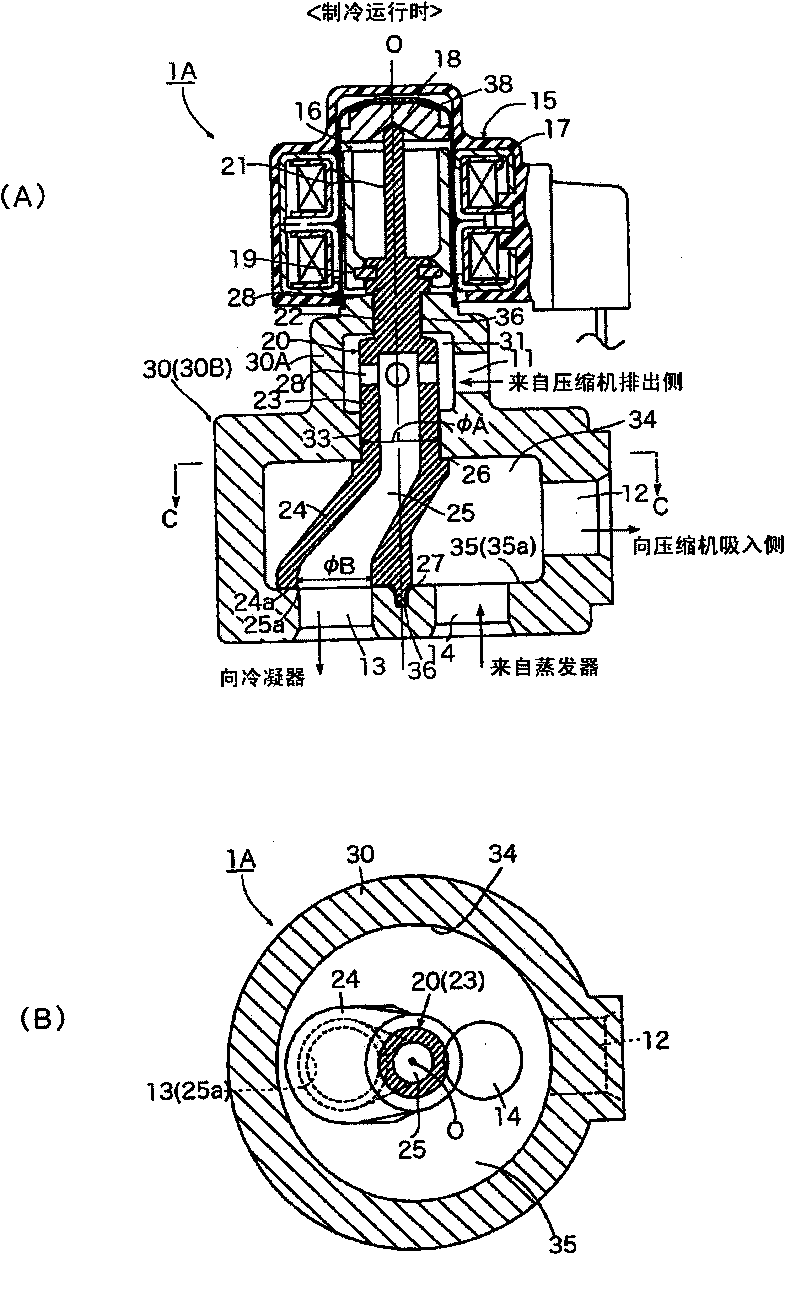
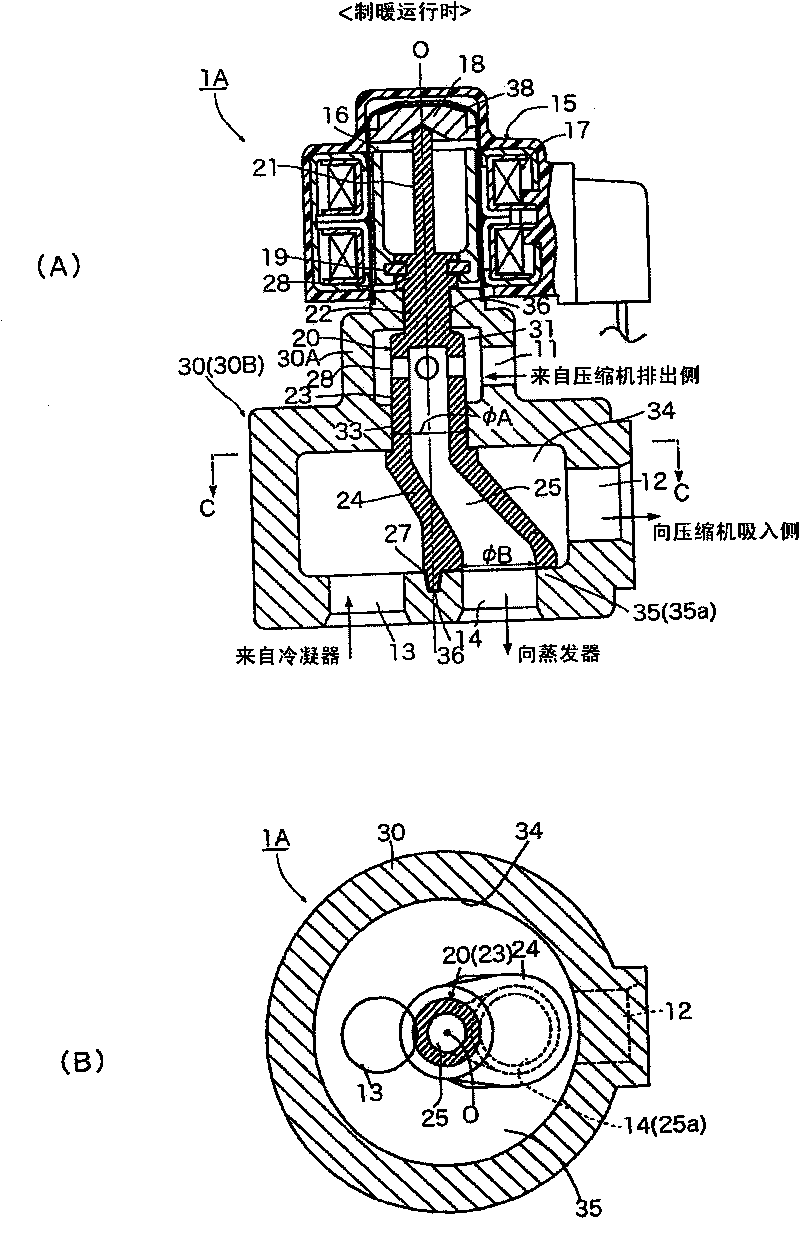
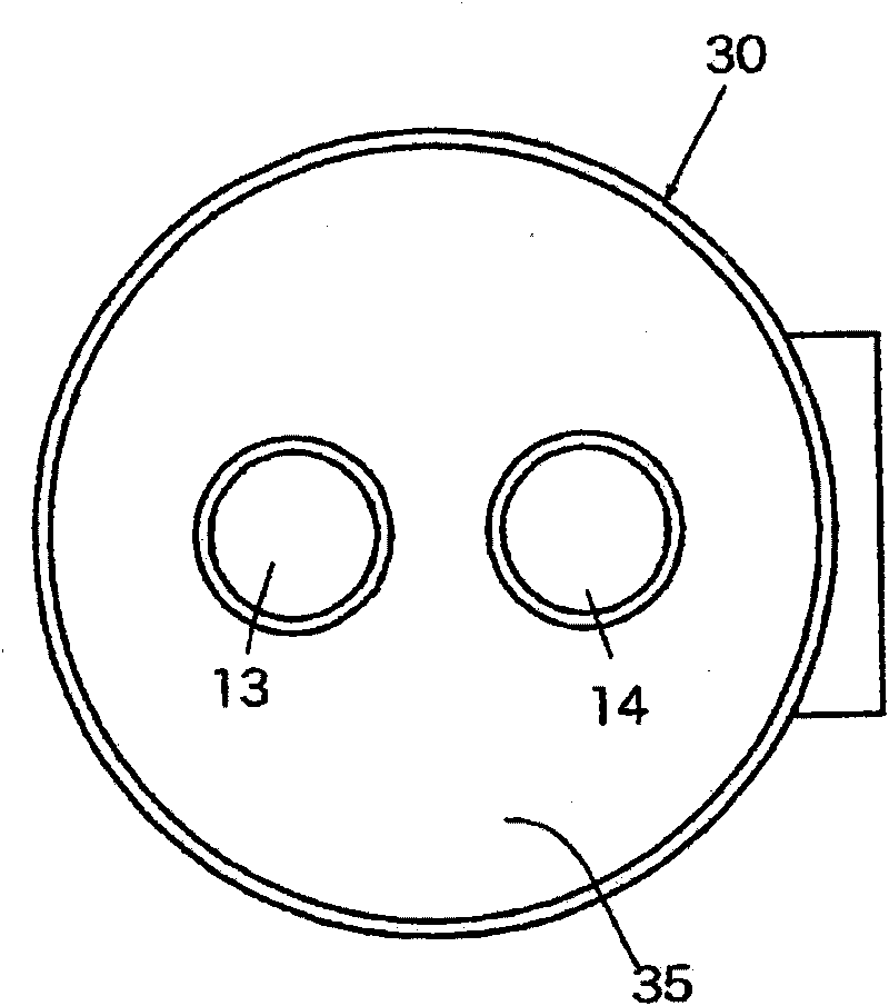
[0084] figure 1 , figure 2 The first embodiment of the multi-way (four-way) switching valve of the present invention shows the state during cooling operation and the state during heating operation. (A) is a longitudinal sectional view, and (B) is a sub-CC of (A) The cross-sectional view of the arrow, image 3 For its bottom view, Figure 4 It is the right view.

[0085] Figure 1 ~ Figure 4 The multi-way switching valve 1A shown is a four-way switching valve used in a refrigeration cycle, etc., and includes: a motor 15 as an actuator for channel switching, which is composed of a rotor 16 and a stator 17, and a valve core 20 that passes through The motor 15 rotates; and the valve body 30, which rotatably holds the valve core 20 and is composed of an upper chamber forming portion 30A and a valve chamber forming portion 30B, and the cross-sec...


PUM


Abstract

To provide a multi-way selector valve properly used for a vehicle, with a smooth flow path switching operation even in case of a large pressure difference between the inside and outside of a valve body, a reduced refrigerant passing noise at a time of switching a flow path, and an easy flow path switching operation, the multi-way selector valve includes a valve body 50 rotated by a flow path switching actuator 15, and a valve main body 60 rotatably holding the valve body 50, the flow path switching actuator is a stepping motor 15 including a rotor 16 placed on the inner peripheral side of a can 38 and a stator 17 placed on an outer periphery of the can 38, and a planetary gear type speed reduction mechanism 40 is inserted between the rotor 16 of the stepping motor 15 and the valve body 50.

Description

Technical field [0001] The present invention relates to multi-way switching valves such as three-way switching valves and four-way switching valves used in refrigeration cycles, etc., and more particularly to a rotary multi-directional switching valve suitable for vehicles, which is actuated by a planetary gear reduction mechanism. The actuator rotates the valve core to switch the flow path. Background technique [0002] Generally speaking, in addition to compressors, gas-liquid separators, condensers (outdoor heat exchangers), evaporators (indoor heat exchangers), and expansion valves, the refrigeration cycles of air conditioners and refrigeration devices also have functions as flow The four-way switching valve of the path (flow direction) switching unit. [0003] reference Picture 12 , Figure 13 An example of a refrigeration cycle having this four-way switching valve will be described. The refrigeration cycle 300 of the illustrated example is the structure of an air conditione...

Claims


Application Information

Patent Timeline
IPC IPC(8): F16K11/074
CPCF16K31/535F16K11/074F16K31/043F16K31/041Y10T137/86839F25B41/20F16K47/04
Inventor 神尾猛梅泽仁志
Owner FUJIKOKI MFG CO LTD
Why Eureka
Eureka Blog
Learn More