

Fluid bearing device and disk device
A technology for fluid bearings and magnetic disk devices, applied in bearing assembly, bearings, electromechanical devices, etc., can solve problems such as increased torque loss, deterioration of lubricants, and increased viscosity of lubricants
- Summary
- Abstract
- Description
- Claims
- Application Information
AI Technical Summary
Problems solved by technology
Method used
Image

Examples
Embodiment 1
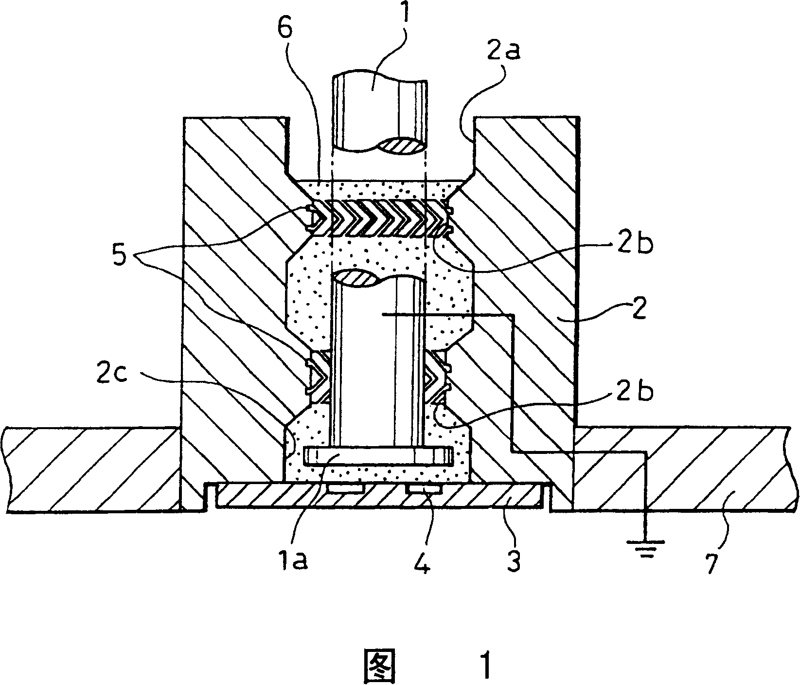
[0039] 1 is a cross-sectional view showing a fluid bearing device according to Embodiment 1 of a hard disk drive (HDD), which is one of magnetic disk devices, using a fluid bearing device according to the present invention.
[0040] As shown in FIG. 1, the fluid bearing device of Embodiment 1 includes: a shaft 1 rotatably configured; Thrust plate 3 disposed facing the end surface (lower surface in FIG. 1 ) of flange portion 1 a formed at the end; lubricant 6 . The lubricant 6 is filled in the gap between the outer peripheral surface of the shaft 1 and the inner surface of the through hole 2 a of the sleeve 2 and the gap between the flange portion 1 a and the thrust plate 3 . The sleeve 2 is integrally formed with the base 7 which is actually fixed on the frame of the hard disk drive (HDD). The thrust plate 3 is mounted on the shaft sleeve 2 and constitutes a shaft sleeve assembly.
[0041] As shown in FIG. 1 , radial dynamic pressure grooves 5 , which are herringbone-shaped ...
Embodiment 2
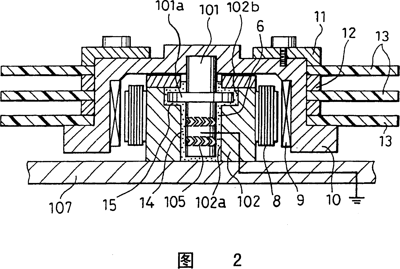
[0057] Next, a hard disk drive (HDD), which is another magnetic disk device using the fluid bearing device according to Embodiment 2 of the present invention, will be described with reference to FIG. 2 .
[0058] 2 is a cross-sectional view showing a case where a fluid bearing device according to a second embodiment of the present invention is used in a hard disk drive (HDD) which is one of magnetic disk devices.
[0059] As shown in FIG. 2 , in the fluid bearing device of the second embodiment, three magnetic disks 13 , 13 , and 13 are stacked on the hub 10 and fixed by a jig 11 . Partition walls 12 are provided between the magnetic disks 13 , and predetermined intervals are provided between the magnetic disks 13 . A rotor magnet 9 is provided on the inner peripheral surface of the hub 10 having an inverted U-shaped cross section. A motor is constituted by the rotor magnet 9 and the stator coil 8 provided on the outer peripheral surface of the boss 102 which is a fixed part....
Embodiment 3
[0069] A case where the fluid bearing device according to the third embodiment of the present invention is applied to the hard disk drive (HDD) shown in FIG. 1 will be described below. The fluid bearing device of the third embodiment has substantially the same structure as the fluid bearing device of the above-mentioned first embodiment except for the structure of the lubricant.
[0070] The base oil of the lubricant of Example 3 is not limited as long as it has a viscosity required for the dynamic pressure generation of the bearing, and may be mineral oil or synthetic oil. Examples of synthetic oils include lubricating oils such as α-olefins (Orefin), grease oils, silicone oils, or fluorine-based oils. The base oil of the lubricant used in Example 3 is the same as the base oil of lubricant 6 in Example 1. In Example 3, a linear linear alkyl sulfonate was added to this base oil. The lubricant of Example 3 was prepared by adding 3% by weight of linear alkyl sulfonate. The el...
PUM
| Property | Measurement | Unit |
|---|---|---|
| electrical resistivity | aaaaa | aaaaa |
| electrical resistivity | aaaaa | aaaaa |
Abstract
Description
Claims
Application Information