Ultrahigh pressure pulse silicon rectifier stack

A pulse rectification and ultra-high voltage technology, applied in electrical components, electrical solid devices, circuits, etc., can solve the problems of low silicon stack frequency, low silicon stack operating voltage, and inability to achieve MHz pulse rectification.

Inactive Publication Date: 2012-07-04
INST OF FLUID PHYSICS CHINA ACAD OF ENG PHYSICS
View PDF7 Cites 0 Cited by
  • Summary
  • Abstract
  • Description
  • Claims
  • Application Information

AI Technical Summary

Problems solved by technology

However, the operating voltage and frequency of the silicon stack are mutually restricted. The silicon stack with high operating voltage has a low frequency, and the silicon stack with high frequency has a low operating voltage. The two cannot be balanced.
Generally, silicon stacks above 100kV can only work below 10kHz, and cannot realize the rectification of MHz pulses

Method used


Image

  • Ultrahigh pressure pulse silicon rectifier stack
  • Ultrahigh pressure pulse silicon rectifier stack
  • Ultrahigh pressure pulse silicon rectifier stack

Examples


Embodiment 1

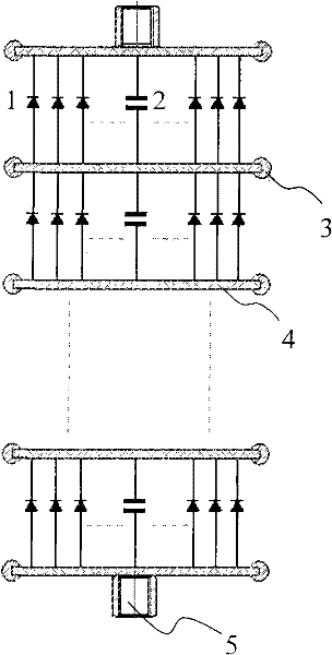
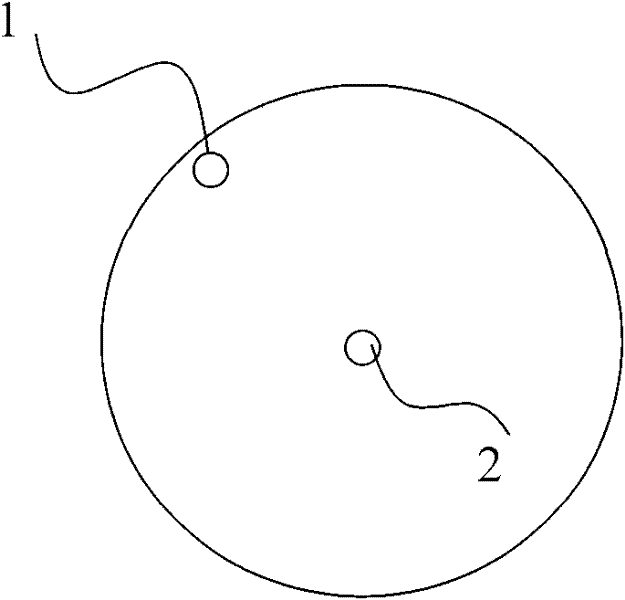
[0023] Embodiment 1: The metal plate in this embodiment adopts a thin metal plate on a double-sided printed circuit board. Diodes are evenly welded on the periphery of the wafer double-sided printed circuit board 4 according to the actual number of parallel connections, and the central part is welded with a voltage equalizing capacitor 2. Each layer is cylindrical, and the whole is also cylindrical. A shim ring 3 is added to the edge of the double-sided printed circuit board 4 of the wafer to homogenize the local field strength, and the number of series series is determined according to the required working voltage. The metal sheets on both sides of the double-sided printed circuit board are electrically connected.

Embodiment 2

[0024] Embodiment 2: The difference between this embodiment and Embodiment 1 is that the metal plate is a whole metal plate, and the diodes and capacitors of two adjacent layers share one metal plate.

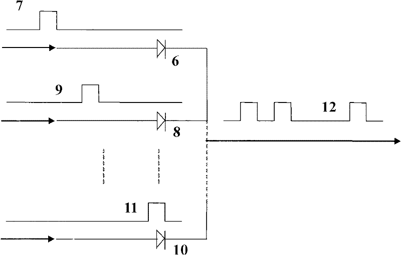
[0025] The purpose of pulse synthesis can be achieved by connecting multiple ultra-high voltage pulse rectifier silicon stacks of the present invention in parallel, such as image 3 . First, the first ultra-high voltage single pulse 7 is delivered to the load through the first ultra-high voltage pulse rectifier silicon stack 6, and at this time, except the first silicon stack is turned on, other silicon stacks are turned off in reverse; then, the second The ultra-high voltage single pulse 9 is delivered to the load through the second ultra-high voltage pulse rectifier silicon stack 8. At this time, except the second silicon stack is turned on, other silicon stacks are turned off in reverse; and so on, the nth ultra-high voltage single pulse The pulse 11 is delivered to the loa...


PUM


Abstract

The invention relates to an ultrahigh pressure pulse silicon rectifier stack, belonging to the technical field of high-frequency rectification. The ultrahigh pressure pulse silicon rectifier stack comprises a plurality of diode layers connected in series, and each diode layer comprises a plurality of diodes which are connected in parallel between an upper metal plate and a lower metal plate, and a voltage-sharing capacitor is also connected in parallel between every two diode layers. The ultrahigh pressure pulse silicon rectifier stack can realize the effectively cutoff of bursting pulses of 300kV or lower than 300kV within 100ns, thereby obstructing inverse voltage; and in addition, the ultrahigh pressure pulse silicon rectifier stack can work at the frequency of 10MHz and lower than 10MHz, thereby solving the problem of high-voltage and high-frequency rectification.

Description

Technical field [0001] The invention relates to high-frequency rectification technology. Background technique [0002] As we all know, silicon stacks are usually used at relatively low frequencies, and most of them are used for rectification. With the development of power electronics, etc., there is a wide demand for ultra-high voltage pulse rectifier silicon stacks. However, the operating voltage and frequency of the silicon stack are mutually restricted. The silicon stack with high operating voltage has a low frequency, and the silicon stack with high frequency has a low operating voltage. The two cannot be balanced. Usually, silicon stacks above 100kV can only work below 10kHz, and cannot realize the rectification of MHz pulses. Contents of the invention [0003] The technical problem to be solved by the present invention is to provide a new type of pulsed silicon stack for ultra-high voltage fast pulse rectification. [0004] The technical solution adopted by the pr...

Claims


Application Information

Patent Timeline
Patent Type & Authority Patents(China)
IPC IPC(8): H01L25/00
Inventor 李欣李劲李远郑容峰
Owner INST OF FLUID PHYSICS CHINA ACAD OF ENG PHYSICS
Why Eureka
Try Eureka