Claw-pole motor

A claw pole motor and end claw technology, applied in the field of claw pole motors, can solve the problems of reducing the torque, power, speed and other performance of claw pole motors, and achieve the effect of reducing reluctance and improving performance

Active Publication Date: 2010-06-16
JING JIN ELECTRIC TECHNOLOGIES (BEIJING) CO LTD
View PDF0 Cites 20 Cited by
  • Summary
  • Abstract
  • Description
  • Claims
  • Application Information

AI Technical Summary

Problems solved by technology

The air gap L1 between the driving end yoke core 151 and the electric end yoke core 152 causes a significant

Method used


Image

  • Claw-pole motor
  • Claw-pole motor
  • Claw-pole motor

Examples


Embodiment Construction

[0045] In order to make the object, technical solution and advantages of the present invention clearer, the present invention will be described in detail below in conjunction with the accompanying drawings and specific embodiments.
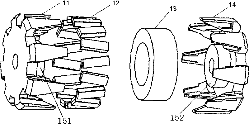
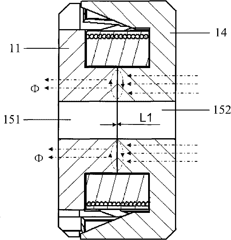
[0046] The basic idea of ​​the present invention is: in the rotor of the claw pole motor, the yoke core is separated from the claw pole, and the yoke core is no longer divided into two parts like the traditional claw pole motor, but the whole yoke The mold core is an independent part, and the yoke mold core and the claw poles are assembled together, so that there is no air gap in the axial direction due to the fitting joint. In the rotor of the claw pole motor of the present invention, due to the fitting assembly The air gap generated by the seam is located in the radial direction, thereby reducing the magnetic pressure drop caused by the air gap generated by the fitting assembly seam, reducing the reluctance, and improving the performance of the c...


PUM


Abstract

The invention discloses a claw-pole motor, which comprises a rotor and a stator. The rotor of the claw-pole motor comprises a driving end claw pole, an electric end claw pole, a magnetic steel assembly, a magnet yoke coil and a magnet yoke die core, wherein the whole magnet yoke die core is used as an independent component, and the magnet yoke die core and the claw poles are assembled together. By adopting the claw-pole motor of the invention, because the air gap produced by the accessory assembly joints inside the rotor is in the radial direction, the size of the secondary air gap caused by a manufacturing process is reduced so as to reduce the magnetic potential drop and magnetic resistance and improve the performance of the claw-pole motor. Moreover, the invention discloses the claw-pole motor assembled by multiple structural compositions so as to simplify the machining and assembly processes of the claw-pole motor.

Description

technical field [0001] The invention relates to motor technology, in particular to a claw pole motor. Background technique [0002] As a driving device that converts electrical energy into mechanical energy output, the motor is widely used in industries, home appliances, automobiles and other fields. Among them, the claw pole motor has a wide range of applications in the automotive field due to its advantages of low structural cost and simple driving circuit. [0003] A traditional claw pole motor consists of a rotor and a stator, and the gap between the rotor and the stator is called the first air gap. figure 1 It is a structural diagram of the rotor of a traditional claw pole motor. Such as figure 1 As shown, the rotor of the traditional claw pole motor includes: driving end claw pole 11, magnetic steel assembly 12, yoke coil 13, electric end claw pole 14, driving end yoke core 151 and electric end yoke core 152, wherein , the drive-end yoke core 151 is integrated with...

Claims


Application Information

Patent Timeline
IPC IPC(8): H02K21/14H02K21/02H02K1/24H02K1/27H02K15/03
Inventor 王江涛王礼恒蔡蔚
Owner JING JIN ELECTRIC TECHNOLOGIES (BEIJING) CO LTD
Why Eureka
Try Eureka