Built-in permanent magnet dual-side flat plate type linear motor

A linear motor and permanent magnet technology, applied in electrical components, electromechanical devices, electric components, etc., can solve the problems of small air gap magnetic density and low thrust density, and achieve higher magnetic density, higher thrust density, and increased maximum torque. The effect of output ability

Active Publication Date: 2010-06-16
HARBIN INST OF TECH
View PDF4 Cites 18 Cited by
  • Summary
  • Abstract
  • Description
  • Claims
  • Application Information

AI Technical Summary

Problems solved by technology

[0003] The purpose of the present invention is to provide a double-sided flat-plate linear motor with built-in permanent magnets, which solves the problems of small air-gap magnetic density and low thrust density in the existing surface-mounted permanent magnet double-sided flat-plate permanent magnet linear motors

Method used


Image

  • Built-in permanent magnet dual-side flat plate type linear motor
  • Built-in permanent magnet dual-side flat plate type linear motor
  • Built-in permanent magnet dual-side flat plate type linear motor

Examples


specific Embodiment approach 1

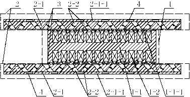
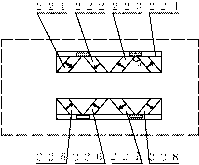
[0011] Specific implementation mode one: the following combination figure 1 and figure 2 Describe this embodiment. This embodiment includes a primary 1 and a secondary 2. The secondary 2 includes two flat-shaped excitation components. The primary 1 is located in the middle of the two flat-shaped excitation components of the secondary 2. Each flat-shaped excitation component There is an air gap 3 between the inner surface and the outer surface of one side of the primary 1; the structures of the two flat-shaped excitation components are mirror-symmetrical;

[0012] Each flat-shaped excitation part is composed of a secondary iron core 2-1 and a plurality of permanent magnets 2-2, and each secondary iron core 2-1 is provided with multiple pairs of slots on the side of the air gap 3, and each slot has a permanent magnet 2-2, and the permanent magnet 2-2 is closely matched with the slot, and the two permanent magnets in each pair of slots and the iron core in the middle form a ma...

specific Embodiment approach 2

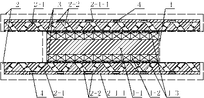
[0020] Specific implementation mode two: combination figure 1 This embodiment is described. The difference between this embodiment and Embodiment 1 is that the material of the back yoke 2 - 1 - 1 of the permanent magnet on the secondary core 2 - 1 is a non-magnetic material. Other components and connections are the same as those in Embodiment 1.

[0021] In this embodiment, the secondary iron core part between the permanent magnets 2-2 adopts a magnetically conductive material, and the back yoke 2-1-1 of the permanent magnet uses a non-magnetically conductive material, which can make the permanent magnet 2-2 leak magnetic circuit reluctance Increase, thereby increasing the magnetic flux of the main magnetic circuit.

specific Embodiment approach 3

[0022] Specific implementation mode three: combination figure 1 Describe this embodiment, the difference between this embodiment and Embodiment 1 or 2 is that there are multiple air slots 4 on the back yoke 2-1-1 of the permanent magnet on the secondary core 2-1, and each air slot 4 The position corresponds to the position of a pair of slots on the secondary core 2-1, and the symmetry line of each pair of slots coincides with the center line of the corresponding air slot 4. Other compositions and connections are the same as those in the first or second embodiment.

[0023] In this embodiment, a plurality of air slots 4 are arranged on the back yoke 2-1-1 of the permanent magnet, and each air slot 4 increases the leakage reluctance between each pair of permanent magnets 2-2 by utilizing the high reluctance characteristic of air , to reduce flux leakage and increase the air gap flux density of the motor.


PUM


Abstract

The invention relates to a built-in permanent magnet dual-side flat plate type linear motor, which belongs to the technical field of motors, and solves the problems of low air gap flux density and low thrust density of the conventional surface-mount permanent magnet dual-side flat plate type linear motor. A secondary pole of the built-in permanent magnet dual-side flat plate linear motor comprises two flat plate type excitation components, a primary pole is positioned between the two flat plate type excitation components of the secondary pole, each secondary iron core is provided with a plurality of pairs of grooves on the air gap side, each permanent magnet is closely matched with the groove in which the permanent magnet is positioned, and two permanent magnets of each pair of grooves and the iron core between the grooves form a magnetic pole; on the lognitudinal cross section of the flat plate type excitation components, the cross section of each groove is a parallelogram, the groove bottoms of the two grooves of each pair of grooves are close to each other and form a V-shape, and the range of the included angle Theta of two adjacent sides of the two grooves in each pair of grooves is not less than 30 degrees and not more than 150 degrees; and the magnetizing direction of each permanent magnet is vertical to the bevel edge of the parallelogram, the magnetizing directions of the two permanent magnet in each magnetic pole are in the same direction or in the opposite directions, and the polarities of the adjacent two magnetic poles are opposite. The invention is a linear motor.

Description

technical field [0001] The invention relates to a double-sided flat-plate linear motor with built-in permanent magnets, belonging to the technical field of motors. Background technique [0002] The traditional linear motion is mostly realized by rotating the motor through synchronous belt, reduction gear and ball screw to convert the rotary motion into linear motion. Due to its complex intermediate transmission mechanism, there are gaps and nonlinear errors, etc., so that the control accuracy of the motor is affected. limit, and the motor wears and makes noise. Now, based on the direct drive technology of linear motors, the realization of linear motion does not need to be converted through complex transmission mechanisms. It has been widely used in machine tools, elevators and other linear motion occasions, and its application fields are gradually expanding to various production and life field. Due to its simple structure and high power index, the bilateral flat linear mot...

Claims


Application Information

Patent Timeline
Patent Type & Authority Applications(China)
IPC IPC(8): H02K41/02
Inventor 李立毅黄旭珍马明娜曹继伟潘东华
Owner HARBIN INST OF TECH
Why Eureka
Try Eureka