Complementary input circularly folding operational transconductance amplifier

An operational amplifier and transconductance technology, used in DC-coupled DC amplifiers, differential amplifiers, etc., to solve problems such as high power consumption and slow OTA speed

Inactive Publication Date: 2010-06-16
TSINGHUA UNIV
View PDF0 Cites 22 Cited by
  • Summary
  • Abstract
  • Description
  • Claims
  • Application Information

AI Technical Summary

Problems solved by technology

[0004] In order to overcome the shortcomings of the existing folding OTA, such as slow speed a

Method used


Image

  • Complementary input circularly folding operational transconductance amplifier
  • Complementary input circularly folding operational transconductance amplifier
  • Complementary input circularly folding operational transconductance amplifier

Examples


Embodiment Construction

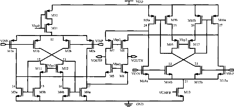
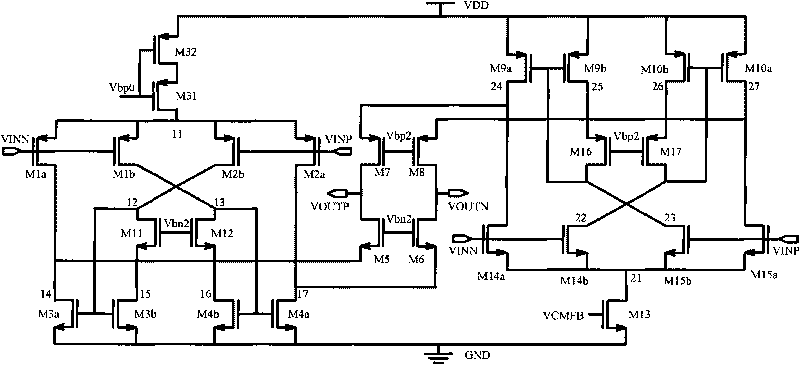
[0019] Technical solution of the present invention refers to figure 1 . figure 1 It is a circular folding OTA with a complementary input, which is different from the conventional OTA. It uses an N-type MOS transistor and a P-type MOS transistor branch complementary input, and both branches are used by Rida S.Assaad and Jose Silva-Martinez in The cyclic folded OTA structure reported in the article "The Recycling Folded Cascode: A General Enhancement of the Folded Cascode Amplifier", Vol. 9, pp. 2535-2542, September 2009, IEEE Journal of Solid State Circuits.

[0020] figure 1The middle transistors M1a, M1b, M2a, and M2b are P-type input devices, and M14a, M14b, M15a, and M15b are N-type input devices. VINP and VINN are fully differential input signals. VINP is added to the gates of M2a, M2b, M15a, and M15b, and VINN is added to the gates of M1a, M1b, M14a, and M14b. Transistors M31, M32 provide bias currents for P-type input branches M1a, M1b, M2a, M2b, and M13 provides bias...


PUM


Abstract

The invention relates to a complementary input circularly folding operational transconductance amplifier, belongs to the technical field of operational amplifiers, and is characterized in that: the unity gain bandwidth of the operational transconductance amplifier is increased through the complementary input of P-type transistors (M1a, M1b, M2a and M2b) and N-type transistors (M14a, M14b, M15a and M15b) and through the adoption of the circularly folding operational transconductance amplifier. A circuit has the advantages of high unity gain bandwidth and low power consumption and accords with the research and development direction of an integrated circuit.

Description

technical field [0001] The invention belongs to the design of ultra-large-scale integrated circuits in the fields of microelectronics and solid-state electronics, and relates to a novel transconductance amplifier circuit, which can be used in the design of analog signal processing circuits such as analog-to-digital conversion circuits and filters. Background technique [0002] The present invention relates to the design of high-speed transconductance operational amplifiers in high-performance switched capacitor circuits such as high-speed analog-to-digital converters. The operational amplifier is one of the most important modules of many analog circuits, and is widely used in analog signal processing circuits such as analog-to-digital conversion circuits and filters. It usually determines the accuracy, speed and power consumption that the high-performance switched capacitor circuit can achieve. In switched capacitor circuits, where the load is usually purely capacitive, a s...

Claims


Application Information

Patent Timeline
IPC IPC(8): H03F3/45
Inventor 魏琦乔飞杨华中汪蕙
Owner TSINGHUA UNIV
Why Eureka
Try Eureka