Method for welding pile leg and pile shoe of drill platform

A welding method and drilling platform technology, applied in welding equipment, metal processing equipment, manufacturing tools, etc., can solve problems such as difficult welding, achieve cost saving, avoid material waste, and facilitate construction

Active Publication Date: 2010-06-23
CHINA MERCHANTS HEAVY IND JIANGSU +1
View PDF0 Cites 14 Cited by
  • Summary
  • Abstract
  • Description
  • Claims
  • Application Information

AI Technical Summary

Problems solved by technology

[0010] The main purpose of the present invention is to address the deficiencies of the prior art, to provide a welding method for the spud legs and spud shoes of the drilling platform, which solves the

Method used


Image

  • Method for welding pile leg and pile shoe of drill platform
  • Method for welding pile leg and pile shoe of drill platform
  • Method for welding pile leg and pile shoe of drill platform

Examples


Embodiment Construction

[0032] The present invention will be further described in detail below through embodiments in conjunction with the accompanying drawings.

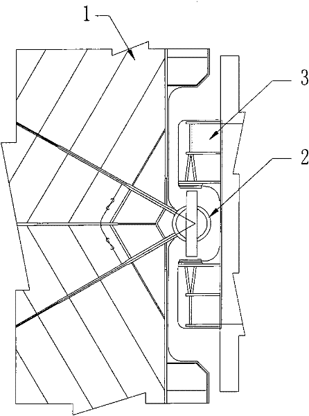
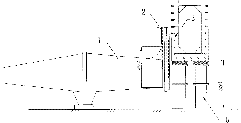
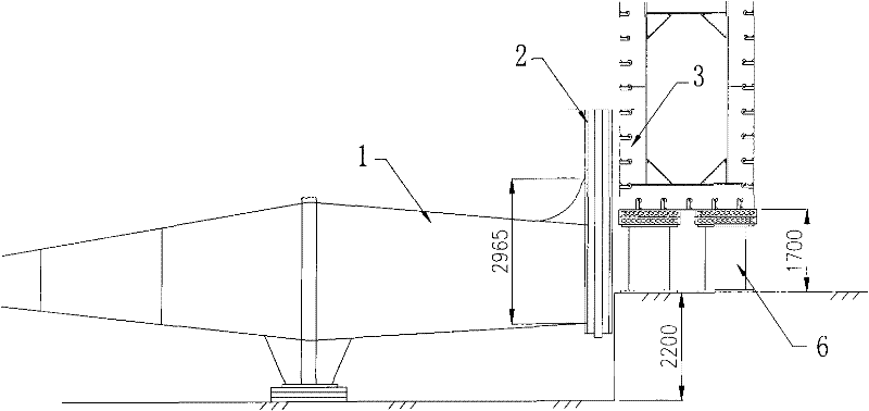
[0033] Please refer to Figures 4a-4d , in one embodiment, the drilling platform includes a spud can and a spud leg 2, the spud can includes a spud can body 1 and a vertical plate member, the position of the spud can body 1 opposite to the spud leg 2 is open, and the vertical plate member has two groups ( Not shown respectively) the first vertical plate 4 (model can be EQ63-Z) and the second vertical plate 5 (model can be EH36-Z), the first vertical plate 4 is rectangular, and described second vertical plate 5 is in A shape with a large curved cutout in a rectangular outline.

[0034] Please refer to Figure 4a-Figure 5 , in a preferred embodiment, the welding method of spud can and spud leg comprises the following steps:

[0035] Step S1. Butt the short side of the first vertical board 4 and the non-arc side of the second vertical boar...


PUM


Abstract

The invention discloses a method for welding a pile leg and a pile shoe of a drill platform. The pile shoe comprises a pile shoe main body and an upright plate component. The method comprises the following steps of: a) welding the upright plate component on the pile leg; b) inserting the upright plate component connected with the pile leg into the pile shoe main body, and c) welding the upright plate component inside the pile shoe main body. The method of the invention solves the problem that the exterior of the pile shoe is difficult to weld because the working station space is narrow. The welding quality is ensured, the welding cost is saved and the construction period is shortened.

Description

technical field [0001] The invention relates to ocean drilling equipment, in particular to a welding method for pile legs and spud cans of a drilling platform. Background technique [0002] For some offshore oil drilling platforms, such as the CJ series platforms designed by Gusto MSC in the Netherlands, the roots of the pile legs are welded on the outside of the spud cans, and the 18 welds will fully bear the lifting weight of the platform (the maximum weight is about 20,950 tons). The importance can be imagined. According to this type of platform structure, the welding seam between the pile leg and the spud can is special, and the space of the welding station is particularly narrow, such as figure 1 As shown, the gap between the spud leg 2, the glideway 3 and the spud shoe 1 is about 135 mm, which is very narrow, so engineers cannot weld from the outside of the spud leg and the spud shoe at all. At present, for the CJ series platforms of Gusto MSC, the major shipyards ha...

Claims


Application Information

Patent Timeline
IPC IPC(8): B23K31/02
Inventor 刘建成
Owner CHINA MERCHANTS HEAVY IND JIANGSU
Why Eureka
Try Eureka