Rigid contact net expansion joint

An expansion joint and rigid contact technology, applied in the direction of overhead lines, etc., can solve the problems of undisclosed pantograph smooth transition, small joint compensation amount, copper braid failure, etc., and achieve good current-carrying performance, large compensation amount, and reduced The effect of the amount used

Active Publication Date: 2010-06-23
浙江旺隆轨道交通设备有限公司
View PDF1 Cites 20 Cited by
  • Summary
  • Abstract
  • Description
  • Claims
  • Application Information

AI Technical Summary

Problems solved by technology

[0004] At present, parallel moving expansion joints are generally used. When installing this joint, two adjacent bus bars (ie, anchor sections) must be arranged in parallel and staggered. Both ends can be retracted, but the compensation amount of this joint is small, only 500 mm, which is only suitable for the expansion and contraction compensation of the short anchor section rigid catenary
[0005] In addition, Chinese Patent No. ZL 02258484.6 also discloses an expansion joint, which is respectively fixed on the adjacent ends of two trolley lines through two adjustment bodies connected by copper braids. The inner conductors of the contact wires are connected to each other, and the copper braid is used to make the current continuous and meet the expansion and contraction of the two trolley wires. The two adjustment bodies are guided by the guide rod between the two adjustment bodies, but the copper The braid is in a state of compression or tension for a long time, which is prone to fatigue damage, resulting in the failure of the copper braid; in addition, the structure does not disclose how the pantograph smoothly transitions from the trolley line to the expansion joint. It can be seen that there is no part in the expansion joint that has the same height as the trolley line, and the pantograph always slides at the same height without fluctuating

Method used


Image

  • Rigid contact net expansion joint
  • Rigid contact net expansion joint
  • Rigid contact net expansion joint

Examples


Embodiment Construction

[0028] The following are specific embodiments of the present invention and in conjunction with the accompanying drawings, the technical solutions of the present invention are further described, but the present invention is not limited to these embodiments.

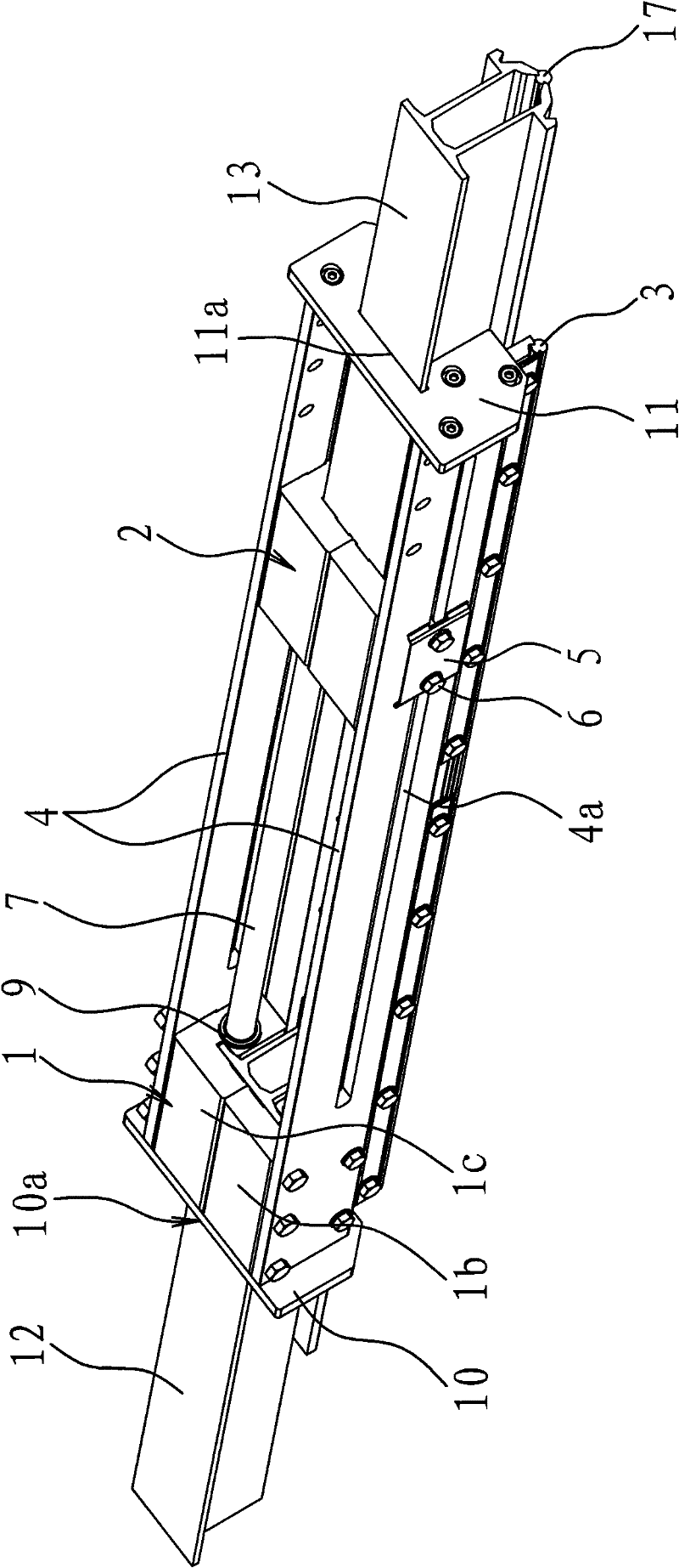
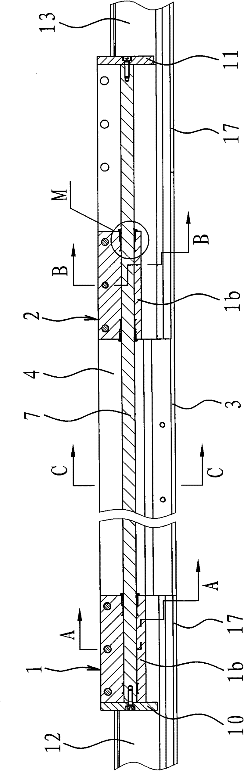
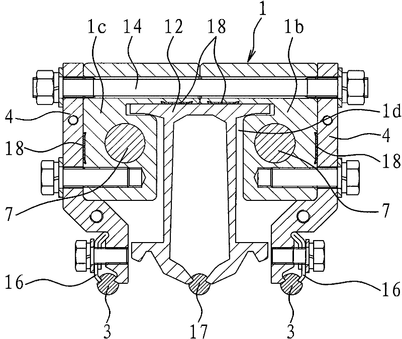
[0029] Such as figure 1 , figure 2 As shown, the rigid catenary expansion joint is connected to the busbars 12, 13, the busbars 12, 13 are fixed on the top of the tunnel through the suspension device, and the bottoms of the busbars 12, 13 are fixed with a contact wire 2 17. The specific structure of this joint includes The fixed joint 1 and the moving joint 2 capable of conducting electricity, the fixed joint 1 is fixed to the connecting end of the bus bar 12, the moving joint 2 is fixed to the connecting end of the bus bar 13, and there are two connecting joints between the fixed joint 1 and the moving joint 2. Or a guide member with electrical conductivity, the guide member includes two guide rails 1 and 4 in the shape...


PUM


Abstract

The invention provides a rigid contact net expansion joint, which belongs to the field of rail transit equipment and solves the problems that the existing expansion joint has low compensation amount to cause high total manufacturing cost and the like. The rigid contact net expansion joint is arranged between two bus bars. The rigid contact net expansion joint is characterized by comprising a fixed joint and a movable joint which can conduct electricity; the fixed joint and the movable joint are used for fixing with the connecting end of one of the bus bars respectively; a guide piece with electric conductivity for connecting the fixed joint and the movable joint is arranged between the fixed joint and the movable joint; the fixed joint is fixed with the guide piece; the movable joint can move along with the guide piece; and a contact line 1 for transmitting current to an electric system of a train is fixedly arranged on the guide piece. The rigid contact net expansion joint is a plug-in expansion joint, and the adjacent two bus bars and the expansion joint are arranged on the same straight line, so the expansion joint is favorable for improving the utilization rate of the bus bars, equivalently improving the length of an anchorage section, and has large compensation amount.

Description

technical field [0001] The invention relates to an expansion joint used for connecting a rigid catenary, belonging to the field of rail transportation equipment. Background technique [0002] Electrified railways and urban rail transit generally use rigid catenary, that is, busbars made of aluminum alloy materials, to carry current. Although the busbars of this material have good electrical conductivity and current-carrying performance, they will change with temperature. resulting in thermal expansion and contraction. [0003] In order to solve the expansion and contraction of the rigid catenary due to temperature changes, the rigid catenary is divided into several segments with a certain length and independent of each other. Each segment is called an "anchor segment". Every two adjacent anchor segments pass through the anchor segment joints. or expansion joints to connect. Although it is simple to set the anchor section joints, serious wear and tear of the contact line wi...

Claims


Application Information

Patent Timeline
Patent Type & Authority Applications(China)
IPC IPC(8): B60M1/24
Inventor 宋晔宏郑志兴徐剑
Owner 浙江旺隆轨道交通设备有限公司
Why Eureka
Try Eureka