Foldable vehicle body

A car body and car body technology, applied in the field of foldable car bodies, can solve the problems of no stacking function, increased manufacturing cost, and failure to make full use of it, and achieve large folding benefits, reduced volume, and space saving Effect

Inactive Publication Date: 2010-06-23
IND TECH RES INST
View PDF3 Cites 15 Cited by
  • Summary
  • Abstract
  • Description
  • Claims
  • Application Information

AI Technical Summary

Problems solved by technology

[0007] But the stretching action of this front vehicle body 20 is to utilize this hydraulic cylinder 22, so this vehicle body must possess enough rigidity, avoids vehicle body to twist, needs quite sophisticated technology in manufacturing and assembling, so increased manufacturing cost; Simul

Method used


Image

  • Foldable vehicle body
  • Foldable vehicle body
  • Foldable vehicle body

Examples


no. 1 example

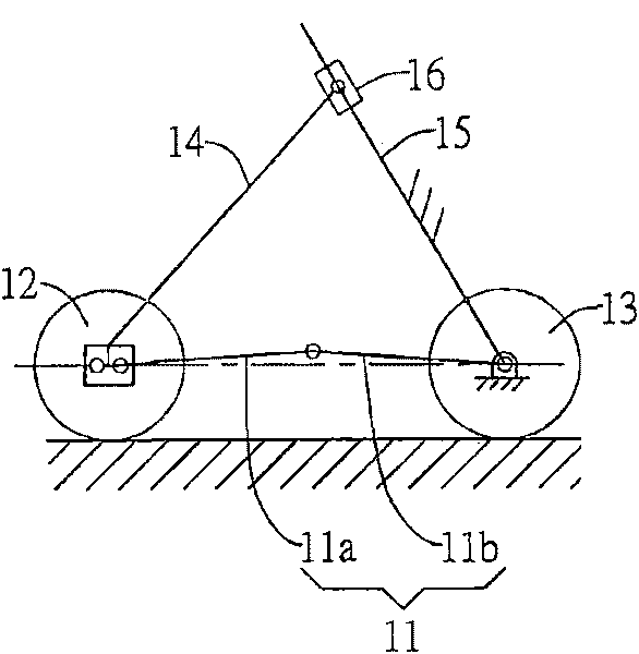
[0069] see Figure 3A , to show a schematic diagram of the first embodiment of a foldable vehicle body of the present invention, the foldable vehicle body 3 of the present invention includes: a vehicle body folding mechanism 31, a chassis folding mechanism 32, and a front wheel mechanism 33 , and rear wheel mechanism 34.

[0070] The vehicle body folding mechanism 31 is a four-bar linkage mechanism composed of the first link 311, the second link 312, the third link 313 and the fourth link 314, which are pivotally connected in series through a rotating joint. , and the body folding mechanism 31 also includes a supporting link group 35 composed of a sixth link 351 and a seventh link 352 pivotally connected in series, wherein the other ends of the sixth link 351 and the seventh link 352 are respectively Pivoted to the first connecting rod 311 and the second connecting rod 312, so as to spread the first connecting rod 311, the second connecting rod 312, the third connecting rod 3...

no. 2 example

[0079] see Figure 4A , to show the schematic diagram of the second embodiment of the foldable vehicle body of the present invention, the vehicle body 4 of the second embodiment of the present invention includes: a vehicle body folding mechanism 41, a chassis folding mechanism 42, a front wheel mechanism 43, a rear Wheel mechanism 44, and rear wheel support link group 45.

[0080] The vehicle body folding mechanism 41 is a four-bar linkage mechanism surrounded by a first link 411 , a second link 412 , a third link 413 and a fourth link 414 to form a space for a user to sit.

[0081] The chassis folding mechanism 42 is located at the bottom of the vehicle body folding mechanism 41, and is pivotally connected to the first connecting rod 411 with one end of the fifth connecting rod 421 through the sliding block 422, so that the fifth connecting rod 421 Sliding and freely swinging on the first connecting rod 411 .

[0082] The front wheel mechanism 43 is located at the pivot joi...


PUM


Abstract

The invention relates to a foldable vehicle body, which comprises a vehicle body folding mechanism, a chassis folding mechanism, a front wheel mechanism and a rear wheel mechanism, wherein the vehicle body folding mechanism is of a four-linkage mechanism formed by a first linkage, a second linkage, a third linkage and a fourth linkage, so as to form a user sitting space; the chassis folding mechanism is arranged at the bottom part of the vehicle body folding mechanism and is pivoted on the first linkage by one end of a fifth linkage; the fifth linkage is provided with a supporting part used for pushing against on the first linkage; the front wheel mechanism is arranged at the bottom part of the vehicle body folding mechanism; and the rear wheel mechanism is pivoted on the other end of the fifth linkage. In the invention, the vehicle body can be folded by adopting the vehicle body folding mechanism and the chassis folding mechanism, and the shaft distance between the front wheel and the rear wheel can be shortened to fully reduce the size of the vehicle body, so as to achieve the stacking effect compared with the same type of vehicle body and greatly save the parking space; furthermore, the foldable vehicle body can be applied to a novel public transportation systems in cities.

Description

technical field [0001] The invention relates to a car body structure, in particular to a foldable car body that can save parking space. Background technique [0002] Due to the advantages of energy saving and low exhaust gas pollution, electric vehicles are becoming more and more popular among consumers. However, due to factors such as battery technology and energy storage technology, the use of electric vehicles is greatly restricted; in recent years, the public transportation system platform It has gradually become the development direction of major metropolitan governments. Its characteristic is that consumers can rent electric vehicles at transportation stations widely distributed in cities, so there is no need to consider issues such as charging and battery life. The platform still exists; therefore, the invention of the foldable or stackable car body structure is used to save the space required for parking, such as European patents such as No. 1066191, No. 1721808, and...

Claims


Application Information

Patent Timeline
IPC IPC(8): B62D21/14B62D21/05B60B35/10B60B31/00B62K15/00
Inventor 朱高弘徐正会
Owner IND TECH RES INST
Why Eureka
Try Eureka