Imaging type method for correcting earth oblateness by earth sensor

An earth sensor and earth flattening technology, applied in the direction of the combined navigator, etc., can solve the problems of accuracy influence, and achieve the effect of accurate geocentric vector and simple operation.

Active Publication Date: 2010-06-23
BEIJING INST OF CONTROL ENG
View PDF0 Cites 18 Cited by
  • Summary
  • Abstract
  • Description
  • Claims
  • Application Information

AI Technical Summary

Problems solved by technology

However, since the moon is a standard spherical shape, there is no oblateness problem, so when the vector method in this paper is applied to th

Method used


Image

  • Imaging type method for correcting earth oblateness by earth sensor
  • Imaging type method for correcting earth oblateness by earth sensor
  • Imaging type method for correcting earth oblateness by earth sensor

Examples


Embodiment

[0131] In order to show the advantages of this method more clearly, an ellipsoid simulation model of the earth is established, and the results after flattening correction are compared with the results of the vector method.

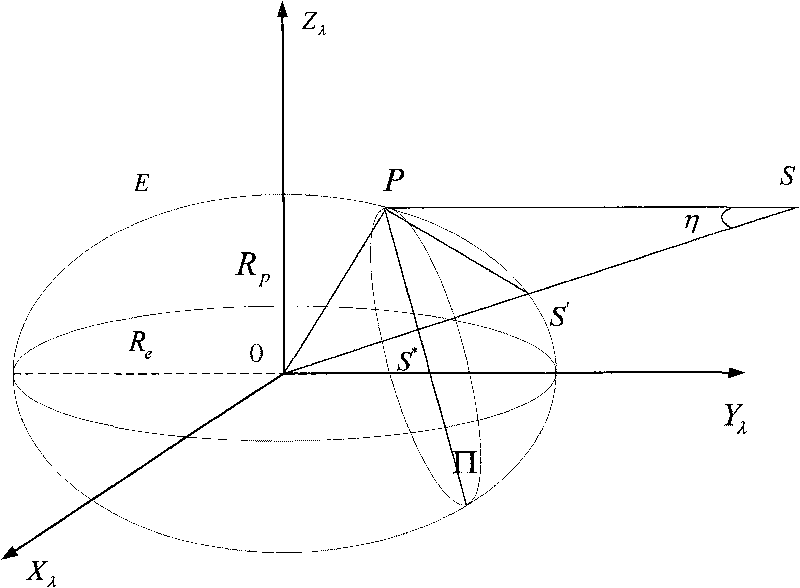
[0132] Assume that the orbital height of a satellite is 500km, the orbital inclination is 80°, and the radius of the earth is R e =6378.14km, the flatness of the earth e=3.292×10 -3 . The installation matrix of the earth sensor is a unit matrix, and the installation angle ξ x = ξ y = ξ z = 0°.

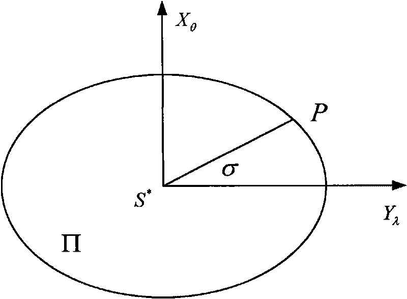
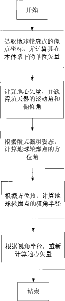
[0133] At a certain moment in the orbital cycle, assuming the attitude of the spacecraft, according to the ideal imaging method, project the points on the contour circle of the earth onto the detector plane, and determine its ideal plane coordinates. Using these plane coordinates as input, first use the spherical model The rolling and pitching attitude of the spacecraft is calculated according to the vector method, and compared with the real attitude; then acc...


PUM


Abstract

The invention discloses an imaging type method for correcting earth oblateness by an earth sensor, which comprises the following steps: extracting a coordinate of an image point of an earth contour point on a photoelectric detector of the sensor and computing a unit vector of the image point in a spacecraft system; assuming the earth is a standard sphere, computing a geocentric vector VEB, and acquiring a rolling angle and a pitch angle Theta of the spacecraft according to the geocentric vector VEB; estimating a yaw angle Psi of the spacecraft at the current moment according to the posture of the spacecraft at previous moment, simultaneously acquiring a current position and a coordinate system transformation matrix of the spacecraft from a spacecraft posture orbit control system, and computing an azimuth angle Sigma of the earth contour point; computing corresponding viewing angle radius Eta according to the azimuth angle Sigma of the earth contour point; and finally, using the viewing angle radius Eta of the earth contour point to remove the influence on the earth oblateness, and acquiring the corrected geocentric vector. The method has simple operation, and can provide more accurate geocentric vector.

Description

technical field [0001] The invention relates to a method for correcting the oblateness of the earth when a space-borne earth sensor is imaging, which can be used to improve the measurement accuracy of the sensor. Background technique [0002] The earth sensor can determine the roll and pitch attitude of the spacecraft through the measurement of the geocentric vector; the combination of the geocentric vector and other celestial vectors (such as star vectors) can also determine the velocity and position of the spacecraft, so the earth sensor is Indispensable for future spacecraft attitude and orbit control systems. [0003] The earth sensor is composed of optical head, sensor and signal processing, and some also include mechanical scanning components. According to whether it contains mechanical scanning components, it can be divided into dynamic scanning type and static imaging type. The dynamic scanning earth sensor uses moving mechanical parts to drive one or more fields o...

Claims


Application Information

Patent Timeline
IPC IPC(8): G01C21/24
Inventor 郝云彩应磊
Owner BEIJING INST OF CONTROL ENG
Why Eureka
Try Eureka