Transformer bushing CT polarity test device based on elimination of impedance and electric arc influence

A transformer bushing and polarity test technology, applied in the direction of measuring devices, measuring electrical variables, instruments, etc., can solve the problems of small secondary induced current, difficult to observe pointer deflection, etc., and achieve the effect of sensitive test response

Inactive Publication Date: 2010-06-23
STATE GRID SICHUAN ELECTRIC POWER COMPANY NEIJIANG POWER SUPPLY
View PDF0 Cites 2 Cited by
  • Summary
  • Abstract
  • Description
  • Claims
  • Application Information

AI Technical Summary

Problems solved by technology

The limitation of this method is that the primary current is already very small, and at the same time, when the coil passes through the current, it will generate magnetic flux, and the magnetic flux of the coil will change. According to Lenz's law, an induced electromotive force in the opposite direction will be induced, which will cause The current of the coil is reduced, and the CT secondary induced current will be even smaller. It is difficult to observe the deflection of the pointer in the actual experiment.

Method used


Image

  • Transformer bushing CT polarity test device based on elimination of impedance and electric arc influence
  • Transformer bushing CT polarity test device based on elimination of impedance and electric arc influence
  • Transformer bushing CT polarity test device based on elimination of impedance and electric arc influence

Examples


Embodiment Construction

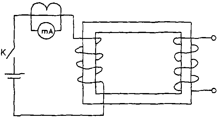
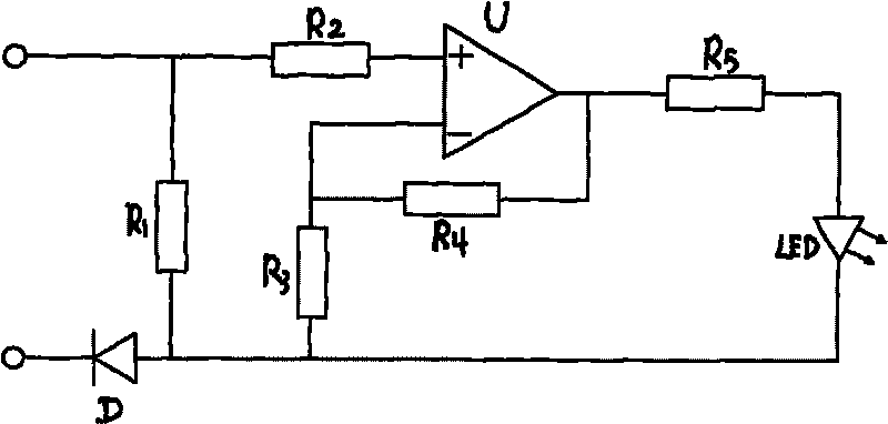
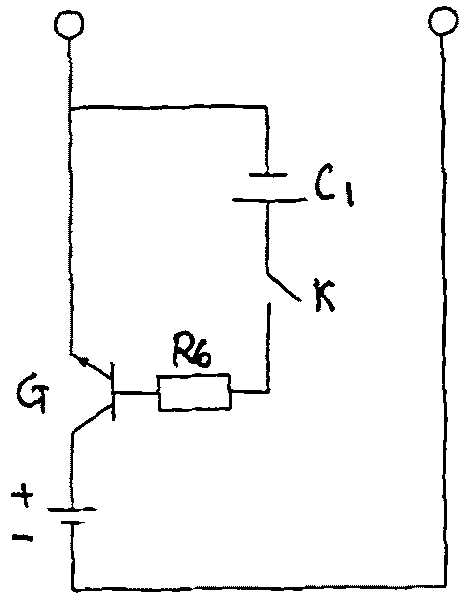
[0014] figure 1 Figure 2 shows that the present invention consists of a CT primary lead access circuit and a CT secondary lead access circuit; the CT primary lead access circuit is: the base of the triode G is connected in series with a resistor R6 and a capacitor C 1 Finally, connect to the emitter of the triode G, the emitter of the triode is used to connect to one end of the CT primary lead, the collector of the triode is connected to the positive pole of the test power supply, and the negative pole of the test power supply is used to connect to the other end of the CT primary lead; CT The secondary lead access circuit is: the positive input terminal of the operational amplifier U is connected to the resistor R 2 One end, resistor R 2 The other end is used to connect to one end of the CT secondary lead, and the negative output end of the operational amplifier U is connected in series with a resistor R 3 It is then connected to the anode of the diode D, the cathode of the ...


PUM


Abstract

A transformer bushing CT polarity test device based on elimination of impedance and electric arc influence is composed of a CT primary lead access circuit and a CT secondary lead access circuit; the CT primary lead access circuit adopts a triode to construct a switch circuit; the CT secondary lead access circuit is composed of an operational amplifier for amplifying the CT secondary current and obtaining more accurate test result. The transformer bushing CT polarity test device tests the amplified CT secondary current and ensures the test result to be accurate and reliable.

Description

technical field [0001] The invention relates to a polarity testing device for a current transformer, in particular to a polarity testing device for a current transformer which reduces the effect of coil inductance by amplifying the secondary induced current of the current transformer. Background technique [0002] The function of the current transformer is to convert the primary current with a large value into a secondary current with a small value through a certain change, which is used for protection, measurement and other purposes, and to isolate primary equipment and secondary equipment. For all directional relay protection, such as 110KV line zero-sequence directional protection, distance protection and main transformer differential protection, the correctness of CT polarity is extremely important. In production, due to the incorrect connection of the polarity of the CT, the power failure accidents caused by the misoperation and refusal of the protection device often oc...

Claims


Application Information

Patent Timeline
Patent Type & Authority Applications(China)
IPC IPC(8): G01R31/06
Inventor 范磊刘武
Owner STATE GRID SICHUAN ELECTRIC POWER COMPANY NEIJIANG POWER SUPPLY
Why Eureka
Try Eureka