Contact type electronic ignition system

A technology of electronic ignition and contact, applied in the direction of induction energy storage device, etc., to achieve the effect of improving dynamic performance, increasing electrode gap, and improving ignition performance

Inactive Publication Date: 2012-03-21
CHENGDU FANXINJIA TECH
View PDF7 Cites 0 Cited by
  • Summary
  • Abstract
  • Description
  • Claims
  • Application Information

AI Technical Summary

Problems solved by technology

Traditional ignition systems can no longer meet these requirements

Method used


Image

  • Contact type electronic ignition system
  • Contact type electronic ignition system

Examples


Embodiment Construction

[0014] The present invention will be further described below in conjunction with the accompanying drawings and specific embodiments.

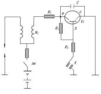
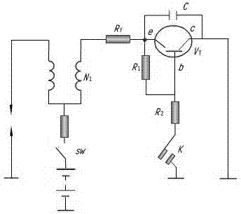
[0015] A contact-type electronic ignition system, including a power supply, an ignition switch, a distributor, an ignition coil primary coil, an ignition coil secondary coil, and a spark plug, is characterized in that it also includes a ballast resistor connected between the ignition switch and the ignition coil primary coil In the primary coil circuit of the ignition coil, an ignition control circuit composed of a triode VT, a resistor and a capacitor is added, and the contacts of the breaker are connected in series in the base circuit of the triode to control the conduction and cut-off of the triode.

[0016] When the ignition switch SW is turned on, when the breaker contact is closed, the base circuit of the triode is connected, making the triode saturated and conducting, and the primary circuit of the ignition coil is connected. The current...


PUM


Abstract

The invention discloses a contact type electronic ignition system which comprises a power source, an ignition switch, a distributor, an ignition coil primary coil, an ignition coil secondary coil, a spark plug, and a ballast resistor, wherein the ballast resistor is connected between the ignition switch and the ignition coil primary coil; and an ignition control circuit which is composed of an audion VT (virtualization technology), a resistor and a capacitor is added in the ignition coil primary coil, a contact point of a breaker is connected in series with a base circuit of the audion and used for controlling the conduction and close of the audion. The ignition system provided by the invention has the advantages of solving the problems that a traditional ignition system provides low secondary voltage and insufficiency spark energy and the like, and preventing the damage to a device caused by heat rush.

Description

technical field [0001] The invention relates to the field of automotive electronics, in particular to a contact type electronic ignition system. Background technique [0002] In recent years, automobile engines are developing toward multi-cylinder, high speed, and high compression ratio. People also try to reduce exhaust pollution and save fuel by improving the combustion condition of the mixture and burning the lean mixture. All of these require that the ignition system of the car can provide sufficiently high secondary voltage, spark energy and optimal ignition time. Traditional ignition systems can no longer meet these requirements. the Contents of the invention [0003] In view of the above-mentioned prior art, the purpose of the present invention is to enable the ignition system to provide sufficiently high secondary voltage and spark energy, while avoiding the thermal run phenomenon of the device. [0004] In order to solve the above technical problems, the presen...

Claims


Application Information

Patent Timeline
Patent Type & Authority Applications(China)
IPC IPC(8): F02P3/04
Inventor 高静袁代华邓金智斯明玉
Owner CHENGDU FANXINJIA TECH
Why Eureka
Try Eureka