Contactless electronic ignition system

An electronic ignition and non-contact technology, applied in spark ignition controllers, engine ignition, induction energy storage devices, etc., to achieve the effects of increasing primary current, improving ignition performance, and increasing secondary voltage

Inactive Publication Date: 2012-04-18
CHENGDU FANXINJIA TECH
View PDF6 Cites 0 Cited by
  • Summary
  • Abstract
  • Description
  • Claims
  • Application Information

AI Technical Summary

Problems solved by technology

Traditional ignition systems can no longer meet these requirements

Method used


Image

  • Contactless electronic ignition system
  • Contactless electronic ignition system

Examples


Embodiment Construction

[0012] The present invention will be further described below in conjunction with the accompanying drawings and specific embodiments.

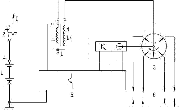
[0013] A non-contact electronic ignition system, including a power supply, an ignition controller, an ignition signal generator, an ignition coil, a spark plug and an ignition switch, is characterized in that: a distributor circuit is integrated on the circuit board of the ignition signal generator, The ignition signal generator is connected with the spark plug and the secondary winding of the ignition coil through wires, and the ignition controller is connected and controlled between the ignition signal generator and the primary winding of the ignition coil; the ignition signal generator with a distributor receives non-electric The piston position signal is converted into a pulse electrical signal and sent to the ignition controller.

[0014] combine figure 1 , turn on the ignition switch, when the ignition signal generator with distributor s...


PUM


Abstract

The invention discloses a contactless electronic ignition system and relates to the automatic electronic technical field, which comprises a power supply, an ignition controller, an ignition coil, a distributor, a spark plug and an ignition switch, and is characterized in that the contactless electronic ignition system comprises an ignition signal generator with the distributor, wherein the corresponding functions of the distributor are integrated on the ignition signal generator with the distributor, the ignition signal generator with the distributor is directly connected with the spark plug and the secondary winding of the ignition coil through leads, and the ignition signal generator with the distributor and the primary winding of the ignition coil are connected and controlled through the ignition controller. The contactless electronic ignition system disclosed by the invention has the advantages that the integration degree is higher, the installation is more convenient, and the ignition property of an engine at high speed is improved.

Description

technical field [0001] The invention relates to the technical field of automobile electronics, in particular to a non-contact electronic ignition system. Background technique [0002] In recent years, automobile engines are developing toward multi-cylinder, high speed, and high compression ratio. People also try to reduce exhaust pollution and save fuel by improving the combustion condition of the mixture and burning the lean mixture. All of these require that the ignition system of the car can provide sufficiently high secondary voltage, spark energy and optimal ignition time. Traditional ignition systems can no longer meet these requirements. the Contents of the invention [0003] The purpose of the present invention is to increase the primary current, increase the secondary voltage, and improve the ignition performance of the engine at high speed without being limited by the contacts. Generally, the low-voltage current of the traditional ignition system does not exce...

Claims


Application Information

Patent Timeline
Patent Type & Authority Applications(China)
IPC IPC(8): F02P3/04F02P7/02
Inventor 高静袁代华邓金智
Owner CHENGDU FANXINJIA TECH
Why Eureka
Try Eureka