Method for repairing liquid crystal display panel using polarized light

A liquid crystal display panel and repair method technology, which is applied in optics, nonlinear optics, instruments, etc., can solve the problems of inability to obtain efficiency and difficulty in linearly polarized light passing through the liquid crystal display panel polarizer uniformly, so as to improve the success rate of repair, Eliminates the effect of light transmission

Active Publication Date: 2010-06-23
CHARM ENG CO LTD
View PDF0 Cites 3 Cited by
  • Summary
  • Abstract
  • Description
  • Claims
  • Application Information

AI Technical Summary

Problems solved by technology

[0015] In such a repair method using linearly polarized light, if the vibration direction of the electric field of the upper polarizing plate 41 and the linearly polarized light passing through it is not exactly coincident, then Good efficiency cannot be obtained, but in fact, considering the process error when making the polarizer and the equipment error of the repair device itself, it is difficult for linearly polarized light to pass through the polarizer of the liquid crystal display panel uniformly

Method used


Image

  • Method for repairing liquid crystal display panel using polarized light
  • Method for repairing liquid crystal display panel using polarized light
  • Method for repairing liquid crystal display panel using polarized light

Examples


experiment example 1

[0067] Figure 7 It is a schematic diagram showing the process of repairing a defective pixel of a liquid crystal display panel according to Experimental Example 1 of the present invention.

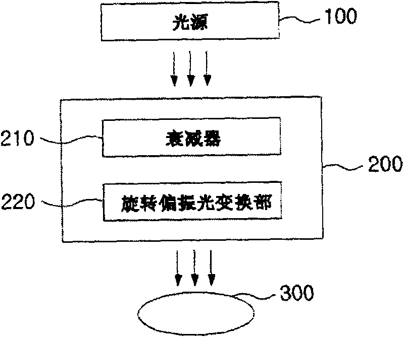
[0068] Such as Figure 7 Shown, in Experimental Example 1 of the present invention, with reference to image 3 The described embodiment of the present invention similarly uses a restoration device including a light source 100 , a light transmission unit 200 , and a light collection unit 300 .

[0069] First, a CW laser having a wavelength of 445 nm was used as a light source, and the laser intensity of the CW laser was adjusted to 75 mW using the attenuator 210 of the light transmission part 200 .

[0070] Then, the light passing through the attenuator 210 is converted into elliptically polarized light by the 1 / 4 wavelength plate in the polarized light conversion unit 220 .

[0071] Next, after the light is transmitted through the upper polarizer 41 corresponding to the green G pixel a...

experiment example 2

[0073] Figure 8 It is a schematic diagram showing the process of repairing a defective pixel of a liquid crystal display panel according to Experimental Example 2 of the present invention.

[0074] Such as Figure 8 Shown, in Experimental Example 2 of the present invention, with reference to image 3 The described embodiment of the present invention similarly uses a restoration device including a light source 100 , a light transmission unit 200 , and a light collection unit 300 .

[0075] First, a CW laser having a wavelength of 445 nm was used as a light source, and the laser intensity of the CW laser was adjusted to 75 mW using the attenuator 210 of the light transmission part 200 .

[0076] Then, the continuous laser light passing through the attenuator 210 is converted into circularly polarized light by using a 1 / 4 wave plate in the rotating polarization conversion unit 220 .

[0077] Next, after the light is transmitted through the upper polarizer 41 corresponding to ...


PUM

PropertyMeasurementUnit
wavelengthaaaaaaaaaa

Abstract

The present invention provides a method for repairing liquid crystal display panel using polarized light, including (a) a step of transforming light emitted from a light source into rectilinearly polarized light; (b) a step of transforming the rectilinearly polarized light to rotary polarized light; (c) a step of eliminating light permeation performance of pixels when the rotary polarized light passes through the polaroid sheet of the liquid crystal display panel.

Description

technical field [0001] The present invention relates to a method of repairing a liquid crystal display panel using polarized light, and more specifically to such a repairing method, that is, using a polarized light conversion component to convert linearly polarized light of laser light into rotationally polarized light (circularly polarized light or elliptically polarized light) ), in order to effectively repair the defective pixels of the LCD panel. Background technique [0002] Recently, as the demand for displays such as cellular phones, PDAs (Personal Digital Assistants) and large televisions increases, technologies related to thinner and lighter flat panel displays are increasingly being developed. [0003] Among such flat panel displays, a liquid crystal display panel used in a liquid crystal display device is a next-generation display device produced by utilizing the birefringence of liquid crystals and the polarizing properties of polarizers. [0004] figure 1 It i...

Claims


Application Information

Patent Timeline
Patent Type & Authority Applications(China)
IPC IPC(8): G02F1/13
CPCG02F1/1309G02F1/133528G02F1/133538G02F1/133541
Inventor 辛圭珹尹星进薛奉浩池泳洙
Owner CHARM ENG CO LTD
Why Eureka
Try Eureka