
Power limiter and power control method

A power limiting and limiter technology, applied in control systems, AC motor control, electrical components, etc., can solve the problems of no technical solution application, and achieve the effect of easy operation, low failure rate, and avoiding power loss of the power grid

Active Publication Date: 2010-06-23
中国船舶重工集团公司第七一二研究所
View PDF0 Cites 10 Cited by
  • Summary
  • Abstract
  • Description
  • Claims
  • Application Information

AI Technical Summary

Problems solved by technology

Large companies such as ABB and SIEMENS have conducted research on this problem, trying to develop their own control systems, but so far, there have been no better technical solutions and successful applications.

Method used


Image

  • Power limiter and power control method
  • Power limiter and power control method
  • Power limiter and power control method

Examples


Embodiment Construction

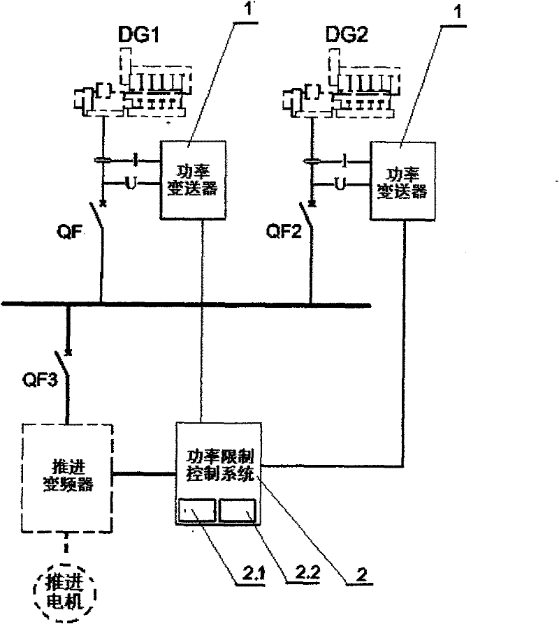
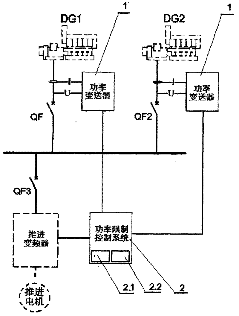
[0026] The power limiter of the present invention is further described as follows with reference to the accompanying drawings and embodiments:

[0027] like figure 1 As shown, a power limiter has a power transmitter 1 and a power limit control system 2; the power transmitter 1 is a conversion module that converts the voltage and current signals of the generator set into active power signals; The power limit control system 2 includes a CPU calculation analysis processing system 2.1 and an online programming communication interface 2.2 for online programming and parameter setting. The power transmitter 1 has a current transformer and a voltage transformer for detecting the active power of each generator set; the output signal of the power transmitter 1 and the signal processed in the power limit control system 2 are 4-20mA current. signal, or a voltage signal equal to or less than +10V, the signal processed in this embodiment is selected as 15mA, may also be selected as 4mA or ...


PUM


Abstract

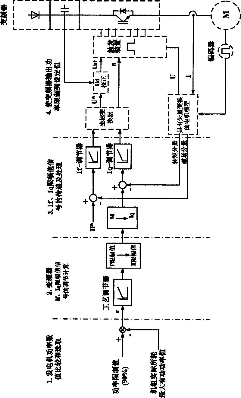
The invention relates to a power limiter and a power control method, which belong to the technical field of electric propulsion. The power limiter comprises a power transducer and a power limiting control system, wherein the power transducer is a conversion module which converts voltage and current signals of a generating set into active power signals; and a power limiting control system comprises a CPU computation and analysis processing system and an online programming communication interface used for online programming and parameter setting. The power control method comprises the following steps of: comparing and selecting a digital power value of the generating set; adjusting and calculating If and Iq amplitude limiting value signals of a frequency transformer; transmitting and processing the If and Iq amplitude limiting value signals; and limiting the output power of the frequency transformer to a set value. The power limiter has the advantages of high intellectualization, capability of being freely embedded into a propulsion frequency transformer control system, convenient operation and implementation, low failure rate and the like.

Description

technical field [0001] The utility model relates to a power limiter and a power control method, which belong to the field of electric propulsion control technology, and are used for real-time monitoring and limiting the size of the propulsion load, so as to match the available load of the power station, so as to avoid the power grid failure caused by the overload trip of the power station unit. Electricity, especially suitable for ship electric propulsion control system. Background technique [0002] In the electric propulsion control system, especially the marine electric propulsion control system, the power and main switch status of all units in the marine power station are collected in real time, and sent to the propulsion inverter after the power transmitter. The state of the switch performs real-time limit control on the thruster power, so as to avoid the power failure of the power grid caused by the overload trip of the unit. This problem is a problem that has been hop...

Claims


Application Information

Patent Timeline
IPC IPC(8): H02P27/04
Inventor 还芳柯常国刘凯洪敏
Owner 中国船舶重工集团公司第七一二研究所
Learn More