
Communication overlay system for dynamic dispatching of carrier channel

A carrier channel and dynamic scheduling technology, applied in wireless communication, electrical components, network planning, etc., can solve the problems of carrier channel resource waste, affect frequency band resource allocation, reduce carrier channel resource utilization, etc., and achieve the effect of simple implementation

Inactive Publication Date: 2012-10-24
COMBA TELECOM SYST (GUANGZHOU) LTD
View PDF0 Cites 0 Cited by
  • Summary
  • Abstract
  • Description
  • Claims
  • Application Information

AI Technical Summary

Problems solved by technology

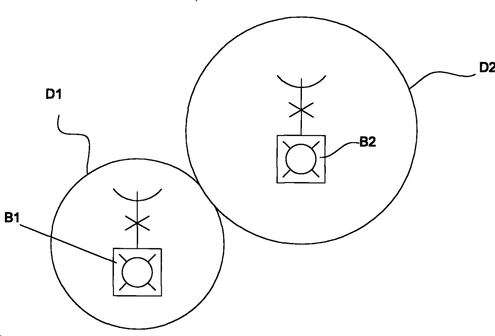
Therefore, when the carrier channel actually required in a certain period of time in the cell D1 is greater than m, the base station B1 cannot meet the service requirements of all users in the cell D1 it covers; if the traffic in the cell D2 is small at this time, it is The number of occupied carrier channels is less than m, for base station B2, it will undoubtedly cause a waste of carrier channel resources
[0004] On the other hand, the actual traffic demand of cells D1 and D2 is a variable, which will change with the characteristics of people's activities. If a higher m value is blindly pursued in order to ensure the normal communication of customers, it will further affect the frequency band resources allocation, reducing the utilization of carrier channel resources
[0005] At present, there are some methods for coordinating carrier channel resources in the industry, but the methods are often limited to the channel adjustment between the coverage network extended from a base station, and there is still room for breakthroughs in its thinking

Method used

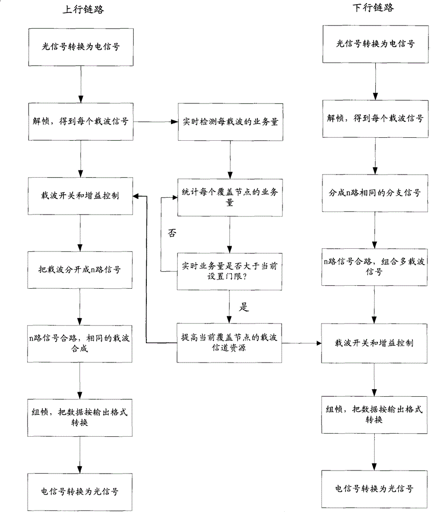

Image

  • Communication overlay system for dynamic dispatching of carrier channel
  • Communication overlay system for dynamic dispatching of carrier channel
  • Communication overlay system for dynamic dispatching of carrier channel

Examples


Embodiment Construction

[0039] Below in conjunction with accompanying drawing and embodiment the present invention will be further described:

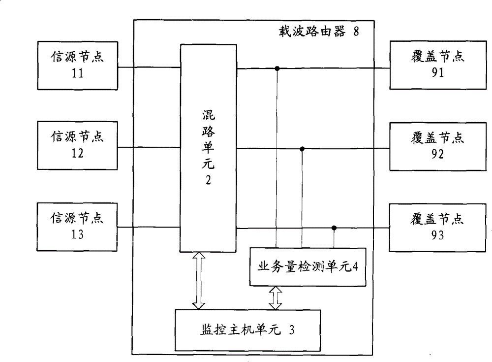
[0040] see image 3 , the communication coverage system of the carrier channel dynamic scheduling of the present invention is a systematic project, which is suitable for the occasions where the mobile communication operators carry out the comprehensive design of the overall coverage.

[0041] image 3 The source nodes 11, 12, 13 generally refer to all node devices used to provide carrier channels or include themselves and node devices extending from themselves. As we all know, source nodes 11, 12, 13 can be base stations, and base stations are A typical carrier channel provider, but it can also be a baseband unit or a remote radio unit in a remote radio system. Although the baseband unit or remote radio unit does not generate a carrier channel by itself, it has the ability to manage the carrier channel from the base station Therefore, in the present inventi...


PUM


Abstract

The invention discloses a communication overlay system for dynamic dispatching of carrier channel, which includes n overlay networks. Each overlay network includes an information source node used for providing a carrier channel and an overlay node used for overlaying the signals carried by the carrier channel of the information source node on each independent space; the system a carrier router, which is respectively and electronically connected with n information source nodes of n overlay networks, and is electronically connected with n overlay nodes of n overlay networks; the communication between the information source node and the overlay node of each overlay network passes through the carrier router; and the carrier router dynamically dispatches the carrier channel between n information source nodes according to the actual demands of the overlay nodes. The communication overlay system for dynamic dispatching of carrier channel has the following advantages that: at first, the communication overlay system for dynamic dispatching of carrier channel breaks through thinking limitation and leads the dynamic dispatching of the resources of the carrier channel to be possible; secondary, the structure is simple, which can dynamically dispatch a plurality of overlay networks through the independent carrier router, thus being convenient for construction and lowering the reconstruction cost.

Description

【Technical field】 [0001] The invention relates to a carrier resource utilization technology in a mobile communication coverage system, in particular to a communication coverage system for dynamic scheduling of carrier channels. 【technical background】 [0002] In the mobile communication coverage system, with the in-depth development of network construction and the continuous improvement of network coverage, the goal of making calls anytime, anywhere has been basically realized. The biggest bottleneck of network development is that the network sacrifices a lot of network indicators in order to meet the business needs of users, which reduces the utilization rate of channel resources in exchange for capacity; on the other hand, the periodic bursts of centralized services cause resource waste and reduce equipment utilization. . [0003] by figure 1 For example, let figure 1 The middle cells D1 and D2 belong to the coverage of the base stations B1 and B2 respectively. Assuming...

Claims


Application Information

Patent Timeline
Patent Type & Authority Patents(China)
IPC IPC(8): H04W16/10
Inventor 伍尚坤龚伟
Owner COMBA TELECOM SYST (GUANGZHOU) LTD
Learn More