Sliding cone structure

A technology of split structure and cone, applied in the field of sliding cone structure, can solve the problems of reduced machining accuracy of boring bars, increased machining cost, inability to guarantee accuracy, etc., and achieves shortened machining length, low machining cost and good use effect. Effect

Inactive Publication Date: 2010-06-30
WUXI WUYE METAL ROLLING
View PDF0 Cites 2 Cited by
  • Summary
  • Abstract
  • Description
  • Claims
  • Application Information

AI Technical Summary

Problems solved by technology

Generally, this kind of long hole is processed by ordinary boring machine. When the length of the hole is too long, the processing accuracy of the boring bar will decrease; if the workpiece is turned around and processed, the same accuracy cannot be guaranteed.
The processing of the sliding keyway 7 is generally processed by a slotting machine. When the length is too long, the accuracy is difficult to guarantee
To ensure the machining accuracy of the sliding cone 4, special processing equipment must be used, such as wire cutting, and the cost of processing will be greatly improved.

Method used


Image

  • Sliding cone structure
  • Sliding cone structure
  • Sliding cone structure

Examples


Embodiment Construction

[0013] The present invention will be further described below in conjunction with the embodiments in the accompanying drawings.

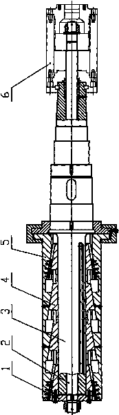
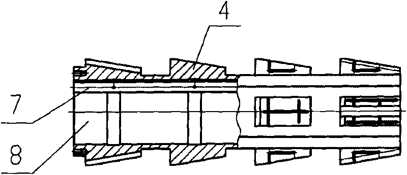
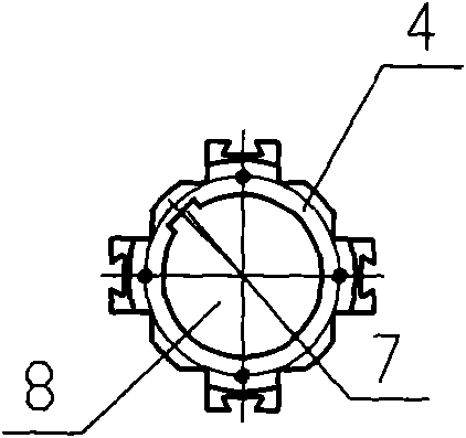
[0014] Such as Figure 4 ~ Figure 6 As shown, including middle hole 8, sliding keyway 7, front cone 9, middle cone 10, rear cone 11, spacer 12, connecting rod 13, process shaft 14, blind hole 15 and through hole 16, etc.

[0015] Such as Figure 4 As shown, it is a schematic view of the expansion and contraction mechanism installed with the reel of the uncoiler of the present invention. Compared with the expansion-contraction mechanism in the prior art, the expansion-contraction mechanism has no change in other parts, but the structure of the sliding cone has been improved.

[0016] The cone of the present invention is a split structure, which is connected into one body by connecting rods 13 . The cone is divided into a front cone 9 , a middle cone 10 and a rear cone 11 , and a spacer 12 is arranged between the front cone 9 and the middle cone 10 ...


PUM


Abstract

The invention relates to a sliding cone structure used in a reel expanding mechanism of a decoiler for metallurgy cold-rolled steel plates. The cones are of separated structures, connected together by a connecting rod. The cones are divided into a front cone, a middle cone and a back cone. Spacer sleeves are installed between the front cone and the middle cone as well as between the middle cone and the back cone. The invention is of a separated structure. An intermediate hole and a sliding keyseat can be processed on the separated bodies. Because of greatly shortened processing length, general-purpose machine tools can be adopted, with low processing cost, simple operation, and good use effect.

Description

technical field [0001] The invention relates to a sliding cone structure, in particular to a sliding cone structure used in the reel expansion and contraction mechanism of a metallurgical cold-rolled steel plate uncoiler. Background technique [0002] Such as figure 1 Shown is the expansion and contraction mechanism of the uncoiler reel in the existing cold rolling mill. The cylinder 6 pushes the core rod 2 in the middle to move axially. The core rod 2 is installed in the main shaft 3. The cross plate 1 fixed on the core rod 2 is connected to the sliding cone 4. When the core rod 2 moves axially, the sliding cone 4 Also for axial movement. The fan-shaped block 5 that can only move radially is installed on the slope of the sliding cone 4. Such as figure 2 , image 3 As shown, since the sliding cone 4 is integral, when its length exceeds one meter, the processing difficulty of the middle hole 8 and the sliding keyway 7 will be greatly increased, and the processing accura...

Claims


Application Information

Patent Timeline
Patent Type & Authority Applications(China)
IPC IPC(8): B21C47/30
Inventor 周小芳蒋红彬
Owner WUXI WUYE METAL ROLLING
Why Eureka
Try Eureka