Heat exchanger

A heat exchanger and heat exchange tube technology, applied in the field of surface coiled tube heat exchangers, can solve the problem of increasing the complexity of system manufacturing and processing, affecting the heat transfer or resistance characteristics of the heat exchanger, and detrimental to the high efficiency and energy saving of the heat exchanger. problems, to achieve the effect of reducing manufacturing and assembly costs, increasing disturbance, and reducing pump power consumption

Active Publication Date: 2013-05-22
XI AN JIAOTONG UNIV
View PDF2 Cites 0 Cited by
  • Summary
  • Abstract
  • Description
  • Claims
  • Application Information

AI Technical Summary

Problems solved by technology

This type of heat exchange structure will seriously affect the heat transfer or resistance characteristics of the heat exchanger. For example, the heat transfer coefficient of laminar flow at low flow rate is low, while the heat transfer coefficient of turbulent flow at high flow rate is high. However, because the flow path of the shell-side fluid is too long, the resistance is very large, and the pumping work of the shell-side fluid is too large, which is not conducive to the heat exchanger to achieve high efficiency and energy saving requirements.
In addition, although devices such as deflector columns and spoilers are used to improve the heat transfer performance, it further increases the resistance of the system, and it is easy to form dirt accumulation in the fluid diversion area, such as the dead corner of the deflector column and spoiler. And increase the complexity of system manufacturing and processing, further reduce system performance

Method used


Image

  • Heat exchanger
  • Heat exchanger
  • Heat exchanger

Examples


Embodiment Construction

[0017] The present invention will be described in further detail below in conjunction with the accompanying drawings.

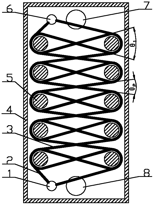
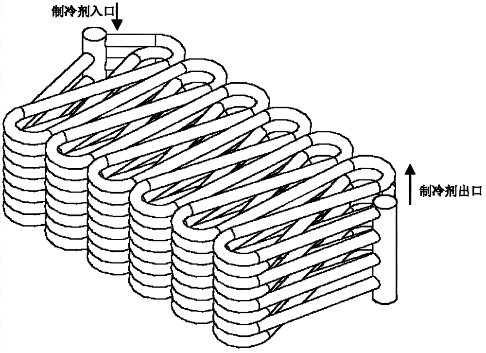
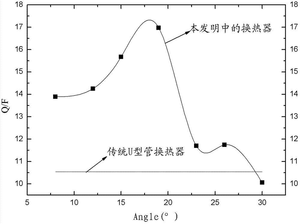
[0018] see figure 1 , 2. The present invention includes a shell 4 provided with a heat exchange working medium inlet 7 and a heat exchange working medium outlet 8, and several layers are arranged in the shell 4 with a refrigerant inlet 1 and a refrigerant outlet 6 without an inner core. Bending tube technology A serpentine heat exchange tube formed at one time. The bend angle of the serpentine heat exchange tube is greater than 180°, and the elbows at both ends are close together (or very close), which greatly reduces the space of the heat exchanger. The volume of the straight pipe section accounts for 70% of the total length. As we all know, when the fluid flows in the straight pipe section, there is only frictional resistance along the way without excessive local resistance caused by the change of flow direction, so the fluid flow in the straight pipe secti...


PUM


Abstract

The invention discloses a heat exchanger. The heat exchanger comprises a shell, and the shell is provided with a heat-exchange working medium inlet and a heat-exchange working medium outlet; the inside of the shell is provided with multiple layers of serpentine heat exchange tubes, each serpentine heat exchange tube is provided with a refrigrant inlet and a refrigrant outlet, and the serpentine heat exchange tubes in two adjacent layers are arranged in a staggered mode; and the inside of the shell is also provided with a positioning column for fixing the serpentine heat exchange tubes. According to the invention, the heat exchange tubes between different layers are arranged in a staggered mesh mode, so that the disturbance of fluid beside the shell is greatly increased, and even under thecondition that the flow velocity of the fluid is small, the disturbance of fluid flowing around the outsides of the tubes can be effectively strengthened, thereby greatly improving the heat transmission coefficient of the fluid beside the shell and the heat transmission performance of the heat exchanger, and enabling the temperature distribution of the fluid beside the shell to be more uniform; in addition, components such as spoilers and flow guide poles and the like generally used in the prior art are removed, and a mode that the fluid alternately flows beside the shell is changed into a small-resistance mode that the fluid flows around the outsides of the tubes, so that the length of the flow path of the fluid beside the shell is reduced, thereby effectively reducing the flow resistance of the fluid beside the shell, lowering the pump power consumption of a system, and achieving an energy saving effect.

Description

technical field [0001] The invention relates to a heat exchanger, especially a surface coil heat exchanger used for two fluids without contact (for example, heat exchange between refrigerant and water). Background technique [0002] In industrial production, all the equipment used to realize the heat exchange of cold and hot fluids are collectively referred to as heat exchangers. It is widely used in many technical fields such as chemical industry, oil refining, atomic energy, construction, machinery, transportation, etc. Such as heaters, coolers, evaporators, condensers, reboilers, etc. in chemical production; and air preheaters, steam superheaters, condensers, and cooling towers in thermal power plants. Various industrial sectors use a variety of heat exchangers according to the needs of the conditions. According to the heat exchange method between hot and cold fluids, heat exchangers can be divided into three categories: partition heat exchangers, contact heat exchanger...

Claims


Application Information

Patent Timeline
Patent Type & Authority Patents(China)
IPC IPC(8): F28D7/08
CPCF28D7/082
Inventor 刘冈云黄昌华蒋志武方真健刘迎文
Owner XI AN JIAOTONG UNIV
Why Eureka
Try Eureka