
Current vortex retarder, generation/start integrated system and control method thereof

An eddy current retarder and integrated system technology, applied in the automotive field, can solve the problems of battery energy consumption, battery damage, and complex structure, and achieve the effects of reducing the weight of the vehicle, reducing energy consumption, and prolonging the service life

Inactive Publication Date: 2010-06-30
JIANGSU UNIV
View PDF0 Cites 15 Cited by
  • Summary
  • Abstract
  • Description
  • Claims
  • Application Information

AI Technical Summary

Problems solved by technology

[0002] The traditional car starting system consists of a battery, ignition switch, starter relay, starter, etc. When the ignition switch is turned on to the STA gear, the starter relay is connected to the starting circuit to provide a large starting torque, and the battery needs to provide a large current to the starter rotor. The biggest disadvantage of the armature winding is: when there are factors that cause the engine to fail to start normally, if the driver frequently puts the ignition switch in the STA position, it will not only consume a lot of battery energy, but also seriously affect the use of the battery. life, or even damage the battery
However, the defect of the current power generation / starting system is that the structure is complex, and there is a limitation that the energy during engine braking cannot be fully converted into electric energy.

Method used


Image

  • Current vortex retarder, generation/start integrated system and control method thereof
  • Current vortex retarder, generation/start integrated system and control method thereof
  • Current vortex retarder, generation/start integrated system and control method thereof

Examples


Embodiment Construction

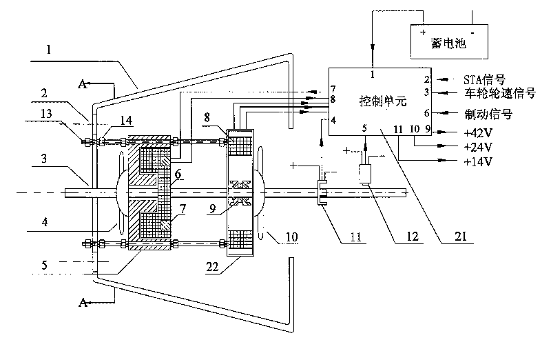
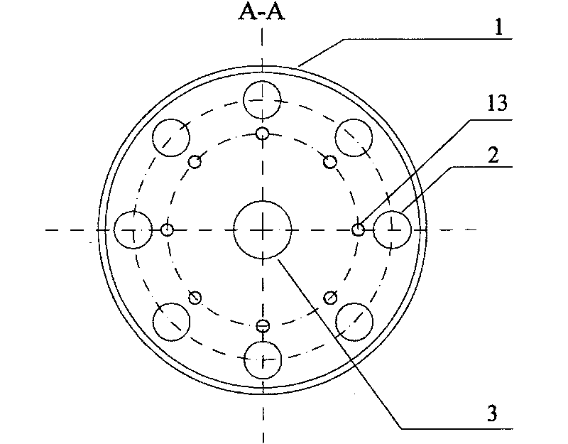
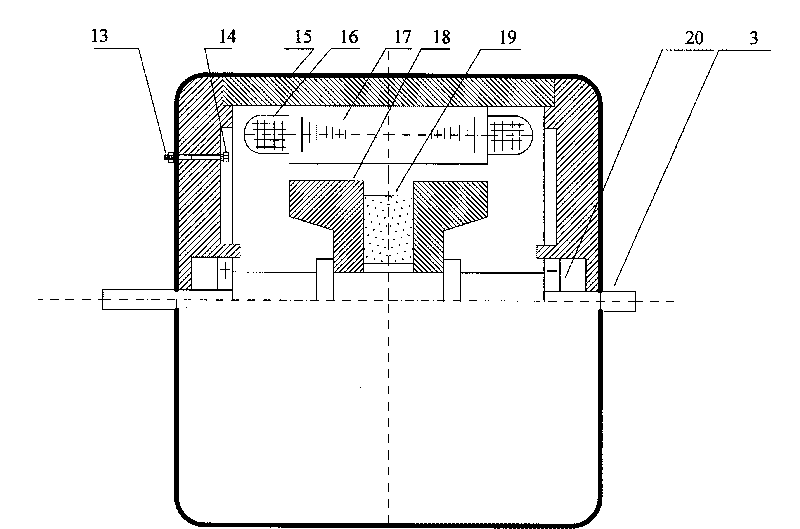
[0023] Such as figure 1 , the present invention is mainly composed of an eddy current retarder 6, a permanent magnet motor 22, a control unit 21, a speed sensor 12, a torque sensor 11 and the like. The present invention cancels the flywheel of the traditional engine, and directly arranges the permanent magnet motor 22 and the eddy current retarder 6 in the flywheel housing 1 . The input shaft 3 passes through the center of the flywheel housing 1 , the eddy current retarder 6 and the permanent magnet motor 22 . On the input shaft 3 in the flywheel housing 1, the eddy current retarder 6 and the permanent magnet motor 22 are fixedly installed, that is, the input shaft 3 is the central axis of the eddy current retarder 6 and the permanent magnet motor 22, in the flywheel housing 1 A speed sensor 12 and a torque sensor 11 are installed on the outer input shaft 3 . The eddy current retarder 6 mainly includes the eddy current retarder fan 4 , the eddy current retarder stator induct...


PUM


Abstract

The invention discloses a current vortex retarder, a generation / start integrated system and a control method thereof in the automobile field. A magnetoelectric machine and a current vortex retarder are arranged in a flywheel casing, an input shaft penetrates through the center of the flywheel casing and fixes the current vortex retarder and the magnetoelectric machine, and a control unit is arranged outside the flywheel casing and is respectively connected with the current vortex retarder, the magnetoelectric machine, a revolution speed transducer, a torque transducer and an accumulator. The control unit monitors the revolution speed of the input shaft to control coils of the current vortex retarder to be electrified so as to start an engine; the control unit also collects the current revolution speed and torque of the input shaft and the wheel speed signals of wheels, calculates the PWM value, and controls the size of the electrified electric current of the current vortex retarder so as to retard the engine. The generation / start integrated system is an intelligentized integrated system which integrates a start system, a generation system and a brake system, thereby reducing the weight. Besides, the produced current vortex brake moment can brake the engine so as to achieve the purpose of recovering the energy, prolong the service life of the accumulator and improve the stability of the brake system.

Description

technical field [0001] The invention relates to the field of automobiles, in particular to a starting system, a power generation system and a braking system of the automobile. Background technique [0002] The traditional car starting system consists of a battery, ignition switch, starter relay, starter, etc. When the ignition switch is turned on to the STA gear, the starter relay is connected to the starting circuit to provide a large starting torque, and the battery needs to provide a large current to the starter rotor. The biggest disadvantage of the armature winding is: when there are factors that cause the engine to fail to start normally, if the driver frequently puts the ignition switch in the STA position, it will not only consume a lot of battery energy, but also seriously affect the use of the battery. life, or even damage the battery. [0003] The traditional automotive power supply system uses an alternator as a power generation device. Due to the limited output...

Claims


Application Information

Patent Timeline
Patent Type & Authority Applications(China)
IPC IPC(8): B60L7/00H02K49/04
CPCY02T10/641Y02T10/64
Inventor 何仁刘存香
Owner JIANGSU UNIV
Learn More