Hydraulic transmission lift truck

A technology for hydraulic transmission and lift trucks, applied in the field of lift trucks, can solve problems such as hidden safety hazards, low mechanical efficiency, enterprise losses, etc., and achieve the effect of reducing labor intensity of workers and improving work efficiency

Inactive Publication Date: 2010-06-30
陈瑞林
View PDF0 Cites 3 Cited by
  • Summary
  • Abstract
  • Description
  • Claims
  • Application Information

AI Technical Summary

Problems solved by technology

There are potential safety hazards in this way of working, which can easily bring danger to the operating workers and cause unnecessary losses to the enterprise.
Moreover, this kind of machinery cannot move forward or backward. If the working position needs to be changed, the machinery must be moved again, resulting in low mechanical efficiency.

Method used


Image

  • Hydraulic transmission lift truck
  • Hydraulic transmission lift truck
  • Hydraulic transmission lift truck

Examples


Embodiment Construction

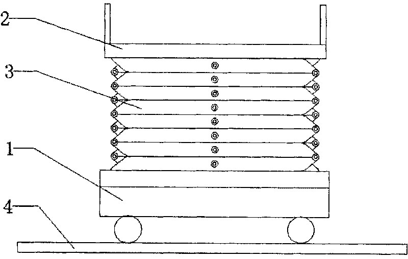
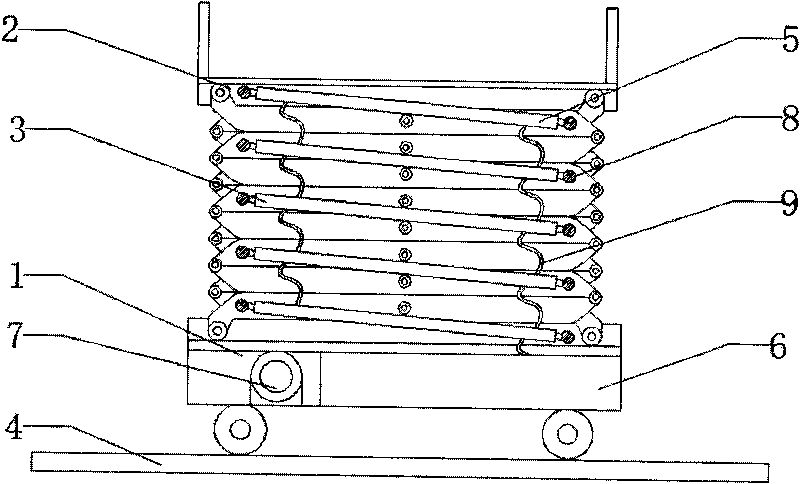
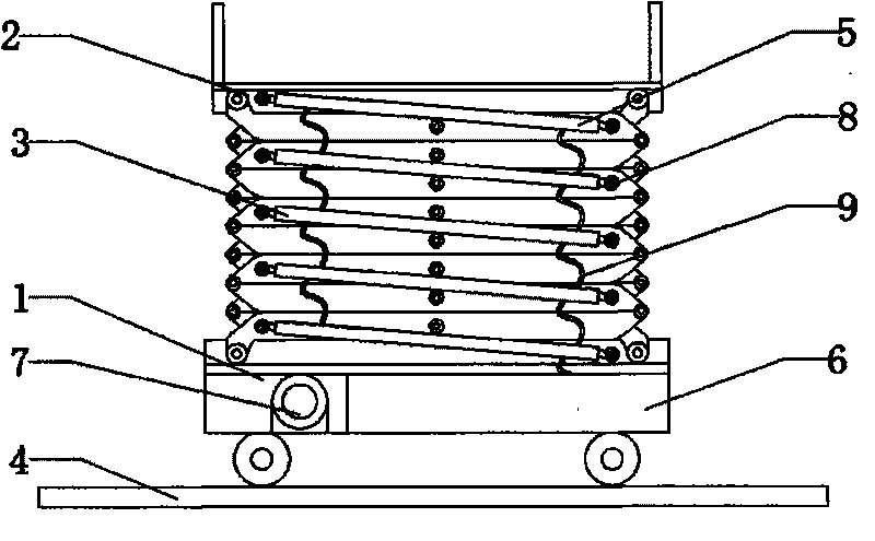
[0021] Such as Figure 1-2 As shown, the hydraulic transmission lift car of the present invention includes a bottom working platform 1, a top operating platform 2, a transmission frame 3, a moving guide rail 4, and a hydraulic system. The bottom working platform 1 is connected with the moving guide rail 4 through rollers, and the bottom working platform 1 is connected with a transmission frame 3 through rollers, and the top of the transmission frame 3 is connected to the top operating platform 2 through rollers. The transmission frame 3 is cross-connected by two "zigzag" frames, and the relative positions Connect with connecting rod 8;

[0022] Described hydraulic system comprises hydraulic column 5, hydraulic pool 6 and drive motor 7, is provided with hydraulic tube 9 and connects hydraulic column 5 and hydraulic pool 6, is connected with drive motor 7 between hydraulic tube 9 and hydraulic pool 6, and the hydraulic pressure The pool 6 and the driving motor 7 are located on ...


PUM


Abstract

The invention relates to a hydraulic transmission lift truck, comprising a bottom working platform, a top operating platform, transmission frames, a mobile guide rail and a hydraulic system, wherein the bottom working platform is connected with the mobile guide rail by idler wheels and is connected with the transmission frames by the idler wheels; the top parts of the transmission frames are connected with the top operating platform by the idler wheels and are in cross-connecting by two zigzag frames, and the relative locations between the transmission frames at two sides are connected by a connecting rod; and the hydraulic system comprises a hydraulic column, a hydraulic tank and a drive motor and is provided with a hydraulic pipe which is connected with the hydraulic column and the hydraulic tank. A drive motor is connected between the hydraulic pipe and the hydraulic tank, the hydraulic tank and the drive motor are positioned on the bottom working platform, and two ends of the hydraulic column are respectively fixed in the middle position of the connecting rod. The hydraulic transmission lift truck has the advantages that the product is applied in a warehouse and a cold storage, the hydraulic transmission lift truck saves time and labor and is safe and reliable after using, the labor intensity of workers is reduced, and the working efficiency can be increased by about 10 times.

Description

technical field [0001] The invention relates to a lifting vehicle, in particular to a lifting device adopting hydraulic transmission. Background technique [0002] At present, most of the lifting parts used by the warehouse lift trucks commonly used at home and abroad adopt the manual lever control operation method. When working, the staff stands and works under the machine. There are potential safety hazards in this way of working, which can easily bring danger to the operating workers and cause unnecessary losses to the enterprise. And this kind of machine cannot move forward or backward. If the working position needs to be changed, the machine must be moved again, resulting in low mechanical efficiency. Based on the above problems, I have designed a hydraulic transmission lift car that uses hydraulic transmission, so that the car can work smoothly under the operation of workers without potential safety hazards, and the rolling pulley design is made at the bottom of the ...

Claims


Application Information

Patent Timeline
Patent Type & Authority Applications(China)
IPC IPC(8): B66F9/22B66F9/075
Inventor 陈瑞林
Owner 陈瑞林
Why Eureka
Try Eureka