Cast-in-place prestressed slab and beam mould, construction method thereof and cast-in-place slab and beam manufactured by same

A prestressed and prestressed tendon technology, applied in the direction of floors, joists, girders, etc., can solve the problems of increasing the amount of steel bars, the weight of the floor body, and the complicated construction, so as to increase the bearing capacity, strengthen the structure, strengthen the effect of structure

Inactive Publication Date: 2010-06-30
张军
View PDF0 Cites 0 Cited by
  • Summary
  • Abstract
  • Description
  • Claims
  • Application Information

AI Technical Summary

Problems solved by technology

[0002] Most of the existing floor slabs and beams are made of non-prestressed solid cast slabs, that is, the whole building is cast-in-situ concrete once the whole building is fixed on the lower side and around the floor of the first floor of the whole building. It is heavy and costly; there are also assembled prestressed hollow slabs, that is, after the prestressed hollow slabs are manufactured in the prefabrication field, they are transported to the site for the second time. A slab is assembled from many pieces of prestressed hollow slabs. Integrity and integrity are poor, and they are not earthquake-resistant; non-prestressed hollow cast slabs are also used, that is, when non-prestressed floor slabs are poured, a number of hollow bodies are filled. Although part of the cement is used less, the amount of steel bars is increased. The weight of the body increases the thickness and increases the cost; there are also post-tensioned prestressed slabs, but they have the characteristics of time delay, complicated construction and high cost.

Method used


Image

  • Cast-in-place prestressed slab and beam mould, construction method thereof and cast-in-place slab and beam manufactured by same
  • Cast-in-place prestressed slab and beam mould, construction method thereof and cast-in-place slab and beam manufactured by same
  • Cast-in-place prestressed slab and beam mould, construction method thereof and cast-in-place slab and beam manufactured by same

Examples


Embodiment Construction

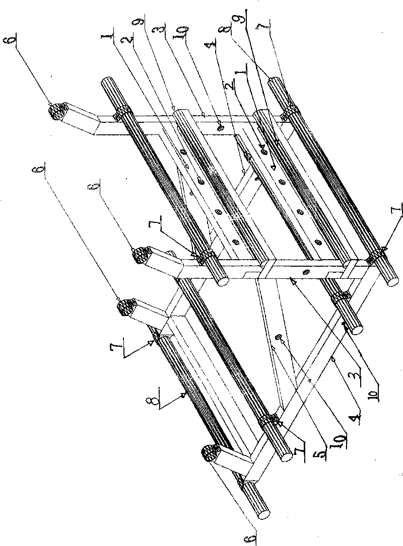
[0030] The concrete cast-in-situ prestressed plate (beam) mold of the present invention will be further described with reference to the accompanying drawings.

[0031] see figure 1, the single mold includes a number of frames (1) connected together, the frame is provided with a number of steel grooves, holes (2), a number of columns (3) perpendicular to the frame at 90 degrees, and a number of vertical columns at 90 degrees The main beam (4), several connecting brackets (5) between the main beam and the column, several support frame seat buckles (6) arranged on the main beam and the column, and several connecting buckle seats arranged on the main beam and the column (7), a number of pipes and columns for the mutual connection and support of several mold monomers arranged on the main beam and the column (8), and a number of pipes and columns for the interconnection of several mold monomers arranged on the main beam and the column. Screw holes (10), straight strips (9) for lev...


PUM


Abstract

The invention relates to a cast-in-place prestressed slab (beam) mould. A monomer of the mould includes a frame which is connected with a main beam together through an upright post and is parallel to the main beam. A plurality of grooves (holes) for fixing prestressed bars are formed on the frame; a prestressed rib leveling straight bar is arranged on the frame; a plurality of screw holes used for mutual connection among a plurality of mould monomers, pipes (columns), pipe (column) buckles and support frame clamping bases are arranged on the uptight column and the main beam; and when the slab (bema) is manufactured by using the mould, two lateral end parts of each of the mould monomers can be connected into a straight shape or a rectangle shape or a shape of a prestressed concrete slab (beam) required to be subjected to cast-in-place on a building object in sequence. In the cast-in-place prestressed slab (beam) mould, because a pretensioned prestressed reinforcing steel bar can be fixed by the grooves (holes) of the prestressed bars formed on the frame, the pretensioned prestressed reinforcing steel bar can be added in the construction of the cast-in-place prestressed slab (beam). The weight of the slab (beam) with the same strength can be greatly reduced. Therefore, the cast-in-place prestressed slab (beam) manufactured by the cast-in-place prestressed slab (beam) mould has the advantages of good integrity, light self-body and low cost.

Description

technical field [0001] The invention relates to a building mould, in particular to a mould for pre-tensioning prestressed concrete cast-in-place slab (beam) on a building body, a construction method thereof, and a cast-in-place prestressed floor slab (beam) produced by the mould. Background technique [0002] Most of the existing floor slabs and beams are made of non-prestressed solid cast slabs, that is, the whole building is one-time cast-in-place concrete after fixing the supporting slabs on the lower side and surrounding of the first floor slab position of the whole building, and there is a slab body. Self-heavy and high cost; there are also assembled prestressed hollow-core slabs, that is, after the pre-stressed hollow-core slabs are fabricated in the prefabrication field, they are transported to the site for the second time. One slab is assembled from many prestressed hollow-core slabs. The integrity and integrity are poor, and it is not earthquake-resistant; there are...

Claims


Application Information

Patent Timeline
Patent Type & Authority Applications(China)
IPC IPC(8): E04C5/12E04C5/18E04G21/12E04B5/32E04C3/26
Inventor 张军
Owner 张军
Why Eureka
Try Eureka