Vertical planetary reducer with temperature control device

A planetary reducer and temperature control device technology, which is applied in the direction of measuring devices, thermometer parts, thermometers, etc., can solve the problems of damaged vertical planetary reducer, poor heat dissipation effect, and rapid temperature rise of the input shaft, etc., to improve Heat dissipation ability, not easy to melt and lose, and prolong the service life

Inactive Publication Date: 2010-06-30
TIANJIN GENERAL PRINCIPLE MACHINERY NEW TECH
View PDF5 Cites 5 Cited by
  • Summary
  • Abstract
  • Description
  • Claims
  • Application Information

AI Technical Summary

Problems solved by technology

Due to the high rotation speed of the input shaft, the temperature inside the machine will rise after working for a long time, especially the temperature of the upper end bearing of the input shaft is the highest. When the grease is not replenished in time during actual work or the transmission of other parts is abnormal, the bearing is prone to failure. Heat research sticking phenomenon, even damage the vertical planetary reducer
[0005] However, t

Method used


Image

  • Vertical planetary reducer with temperature control device
  • Vertical planetary reducer with temperature control device
  • Vertical planetary reducer with temperature control device

Examples


Embodiment 1

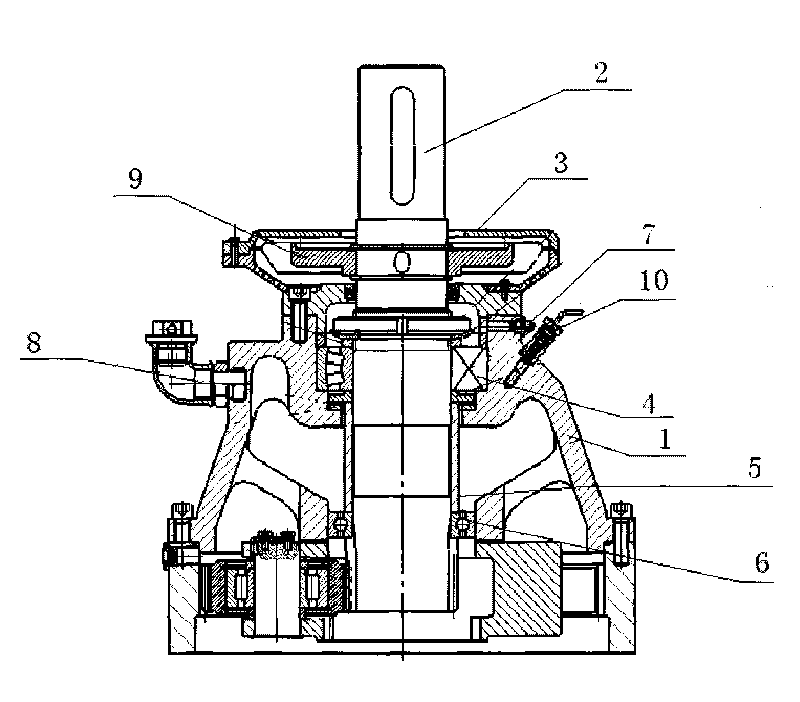
[0029] figure 2 It is a schematic diagram of the overall structure of the vertical planetary reducer with temperature control device of the present invention, as shown in the figure:

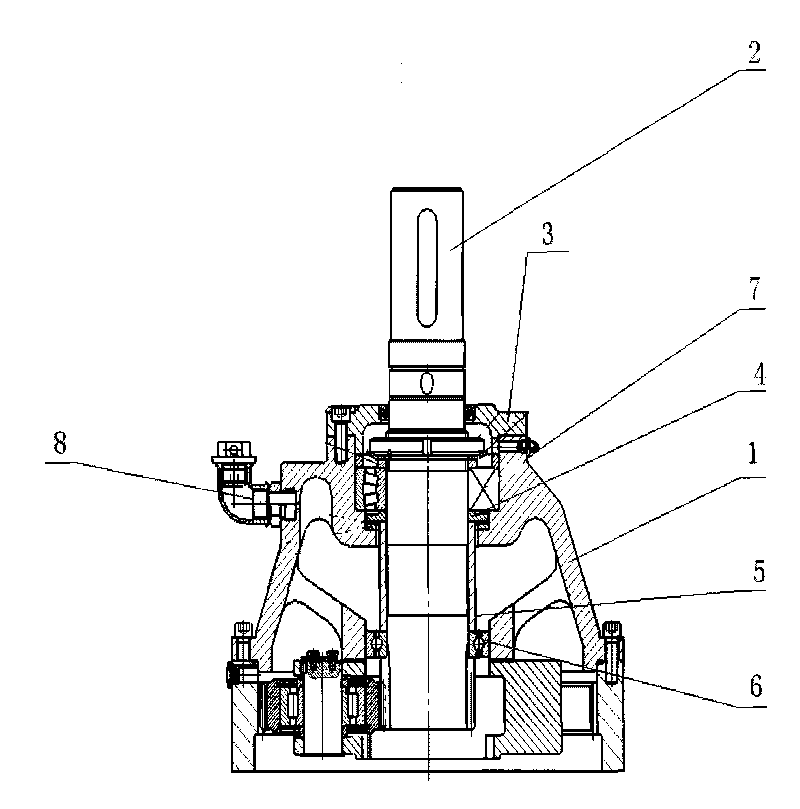
[0030] A vertical planetary reducer with a temperature control device, the temperature control device is composed of an input shaft cooling device and a temperature monitoring device 10, wherein the input shaft cooling device is composed of a fan 9, an air vent 7 and a grease nozzle 8 .

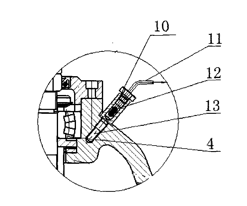
[0031] image 3 It is a schematic structural diagram of the temperature monitoring device of the vertical planetary reducer with a temperature control device in the present invention, as shown in the figure:

[0032] The temperature monitoring device 10 is composed of a temperature measuring contact 13 , a temperature measuring element 12 and an output data line 11 connected in sequence.

[0033] combined with figure 2 , 3 , the technical solution of the present invention is described in detail as follow...

Embodiment 2

[0038] The fan 9 installed can adopt a kind of fan of self-contained drive motor, and this fan comprises motor and fan blade, and wherein motor comprises housing, stator, rotor and motor shaft; Fan blade is fixed on the motor shaft, drives fan 9 and input Axis 2 realizes synchronous rotation.

[0039] When working, the fan 9 can be independently driven and controlled by its built-in motor, and can be started and rotated synchronously with the input shaft 2 on the input shaft 2 .

[0040] Practice has proved that a vertical planetary reducer with a temperature control device in the present invention has the following advantages:

[0041] 1. Equipped with an input shaft cooling device; the structure of the input end cover is improved, and a fan is installed in the input end cover to ventilate and dissipate heat in time, which improves the internal heat dissipation capacity of the reducer, makes the grease difficult to melt and lose, and the bearing can always be fully lubricated...


PUM


Abstract

The invention provides a low-cost vertical planetary reducer with a temperature control device. The device consists of a machine body, an input shaft, an input end cover, a self-aligning bearing, an input shaft sleeve, a locating ball bearing, a vent hole, a greasing fitting, a temperature measuring contact, a temperature measuring component, an output data line and a fan. The device is provided with an input shaft heat dissipating device and a temperature monitoring device and can dissipate heat in time to improve the heat dissipating capability of the inside of the reducer. When the temperature measuring component sends alarm signals, the damage on the bearing can be prevented. The reducer has long serve life, improves grease utilization factor, reduces oil dirt and can meet the market requirements completely. The cost performance of the invention is leading at home.

Description

technical field [0001] The invention relates to a reducer, in particular to a vertical planetary reducer with a temperature control device. Background technique [0002] Usually, the traditional vertical planetary reducer generally adopts such as figure 1 Its structure includes body 1, input shaft 2, input end cover 3, self-aligning bearing 4, input shaft sleeve 5, positioning ball bearing 6, vent hole 7, grease nozzle 8, etc., and its disadvantage is the traditional The input shaft of the vertical planetary reducer adopts natural heat dissipation, and the effect is very poor, because the upper bearing of the input shaft is lubricated with grease. When the temperature of the reducer is too high, the grease melts and loses, and the bearing will be damaged due to lack of oil, and even affect the operation of the machine. [0003] And the working environment temperature of the vertical planetary reducer is usually -10°C-40°C; there are two types of internal lubrication methods...

Claims


Application Information

Patent Timeline
IPC IPC(8): F16H57/04G08B21/18G01K1/02
Inventor 王德禄
Owner TIANJIN GENERAL PRINCIPLE MACHINERY NEW TECH
Why Eureka
Try Eureka