Lens array device and image display

A lens array and lens technology, applied in image communication, instrumentation, optics, etc.

Inactive Publication Date: 2010-06-30
SONY CORP
View PDF3 Cites 41 Cited by
  • Summary
  • Abstract
  • Description
  • Claims
  • Application Information

AI Technical Summary

Problems solved by technology

Therefore, the wavefront 201 of the transmitted light is a plane wave, and the lens array becomes a state where there is no lens effect

Method used


Image

  • Lens array device and image display
  • Lens array device and image display
  • Lens array device and image display

Examples


no. 1 example

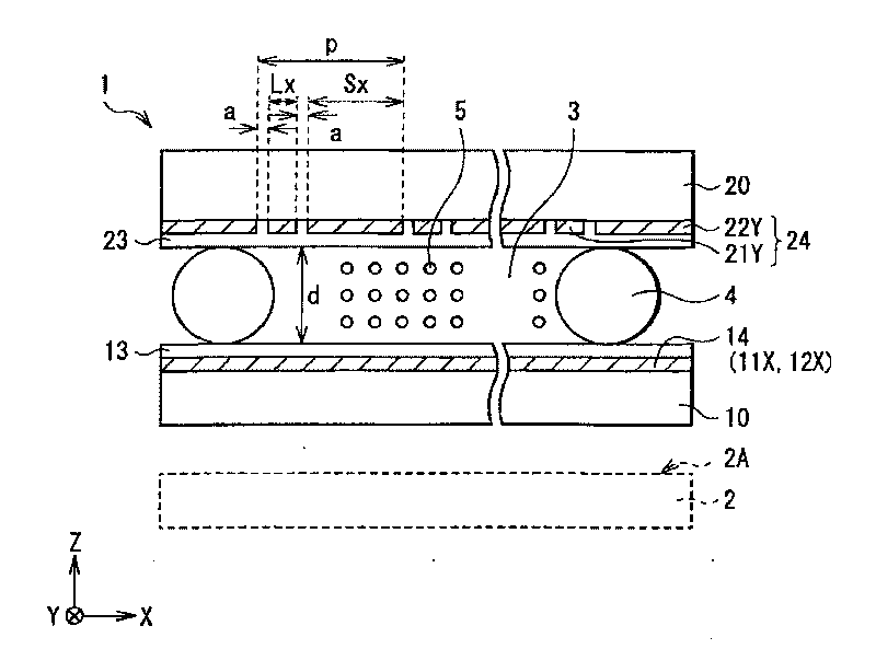
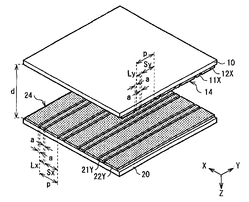
[0047] Overall Construction of Lens Array Device and Image Display

[0048] figure 1 A configuration example of the lens array device 1 according to the first embodiment of the present invention is illustrated. The lens array device 1 includes a first substrate 10 and a second substrate 20, and a liquid crystal layer 3 disposed between the first substrate 10 and the second substrate 20, wherein the first substrate 10 and the second substrate 20 facing each other with a distance d. The first substrate 10 and the second substrate 20 are transparent substrates made of, for example, a glass material or a resin material. The side of the first substrate 10 facing the second substrate 20 is formed with a first electrode group 14 in which a plurality of transparent electrodes extending in the first direction are spaced in parallel in the width direction layout. The alignment film 13 is formed on the first substrate 10 , and the first electrode group 14 is located between the alig...

no. 2 example

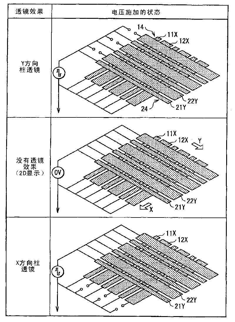
[0073] A lens array device and an image display according to a second embodiment of the present invention will be described below. The same components as those of the lens array device 1 and the image display according to the first embodiment are denoted by the same reference numerals and will not be further described.

[0074] In the lens array device 1 according to the first embodiment, in the image 3 In the case of the driving method shown to realize the applied state of the driving voltage to the upper and lower transparent electrodes, there is a possibility that the shape of the lens (the alignment state of the liquid crystal molecules 5) changes with time, and thus the liquid crystal layer cannot be 3 Control to the desired lens state. In particular, in the case of narrowing the spacing between electrodes (distance d between substrates) to achieve higher resolution and higher response speed, etc., there is a possibility that the liquid crystal layer 3 is not controlled...


PUM


Abstract

The lens array device includes: first and second substrates; a first electrode group formed on the first substrate to include transparent electrodes extending in a first direction; a second electrode group formed on the second substrate to include transparent electrodes extending in a second direction; and a liquid crystal layer with refractive index anisotropy arranged between the first and second substrates to produce a lens effect by changing the liquid crystal molecule alignment. The liquid crystal layer electrically changes into one of three states according to voltages applied to the first and second electrode groups. The three states include a state with no lens effect, a first lens state where a lens effect of a first cylindrical lens extending in the first direction is produced, and a second lens state where a lens effect of a second cylindrical lens extending in the second direction is produced.

Description

technical field [0001] The present invention relates to a lens array device capable of controlling a lens effect by using liquid crystal, and an image display capable of electrically switching between, for example, two-dimensional display and three-dimensional display by using the lens array device to switch. Background technique [0002] In the prior art, binocular or multi-ocular stereoscopic displays are known, which achieve stereoscopic vision by displaying parallax images to both eyes of an observer. In addition, one way to achieve more natural stereoscopic vision is spatial imaging stereoscopic display. In spatial imaging stereoscopic display, multiple light rays with different emission directions are emitted into space to form spatial images corresponding to multiple viewing angles. [0003] As one method of realizing such stereoscopic display, it is known, for example, to combine a two-dimensional display, such as a liquid crystal display, with an optical device fo...

Claims


Application Information

Patent Timeline
Patent Type & Authority Applications(China)
IPC IPC(8): G02F1/13G02B27/22G02B30/27
CPCG02B27/2214H04N13/0404G02F2001/291H04N13/0454H04N13/305H04N13/359G02B30/27G02F1/291G02F1/1335
Inventor 高桥贤一
Owner SONY CORP
Why Eureka
Try Eureka