Oil cooler of traction transformer of electric motor unit

A traction transformer and oil cooler technology, which is applied in the direction of transformer/inductor cooling, etc., can solve the problems that the power variation range of the traction transformer cannot be satisfied, the power variation range of the cooler is small, and the temperature rise of the transformer is increased, and the structure is compact , stable and reliable operation, and low operating noise

Active Publication Date: 2010-06-30
JIANGSU JOSUN SCI&TECH CO LTD
View PDF0 Cites 6 Cited by
  • Summary
  • Abstract
  • Description
  • Claims
  • Application Information

AI Technical Summary

Problems solved by technology

[0005] In order to solve the problem of the integrated structure of the traction transformer cooler in the prior art, the manufacturing and use costs are high, the maintenance and replacement are inconvenient, the power variation range of the cooler is small, and the power variation range of the traction transformer cannot be satisfied, and the cooling effect is reduced. The temperature rise is increased, the efficiency of the transformer is reduced, and the service life is short. The purpose of the present invention is to provide a split structure, which is compact and easy to maintain. It can adapt to the wide range of power variation of the traction transformer and has a good cooling effect on the transformer. , stable operation of the transformer, and long service life of the electric train unit traction transformer oil cooler

Method used


Image

  • Oil cooler of traction transformer of electric motor unit
  • Oil cooler of traction transformer of electric motor unit
  • Oil cooler of traction transformer of electric motor unit

Examples


Embodiment Construction

[0018] The present invention will be further described below with reference to the accompanying drawings and examples.

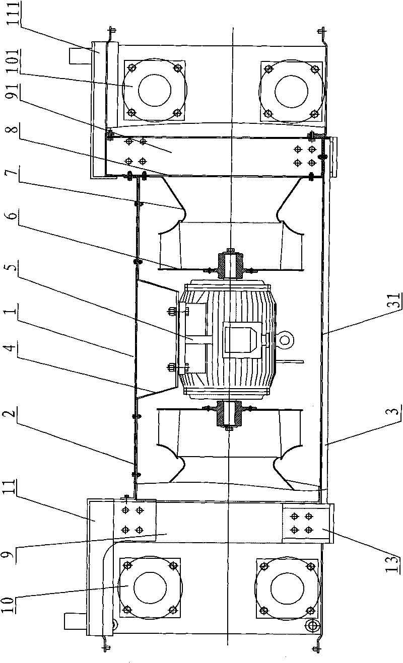
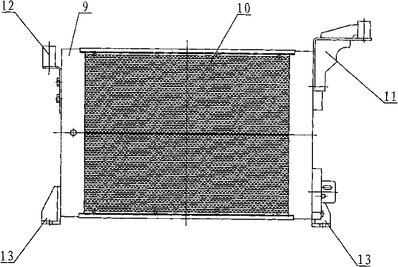
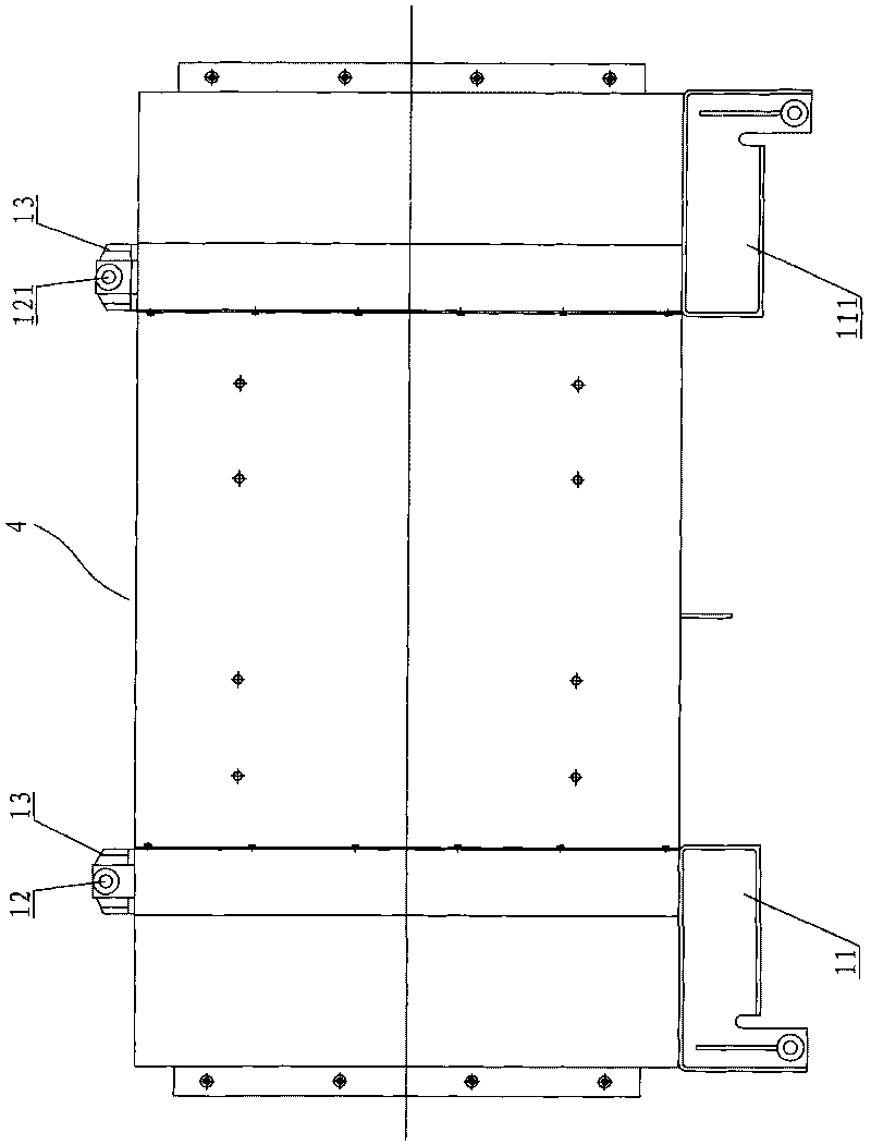
[0019] Figure 1-3 As shown, the electric multiple unit traction transformer oil cooler includes a fan box 1, a motor bracket 4, a two-speed two-axis motor 5, an impeller 6, an air inlet 7, an air inlet box 9,91 and heat exchangers 10,101. The fan box 1 is connected between the two air inlet boxes 9,91, and the two air inlet boxes are respectively connected with the two heat exchangers 10,101. Hole 8, the upper part of one side of the two air intake boxes is respectively connected to the transformer support 11, 111, the upper part of the other side of the two air intake boxes is respectively connected to the oil pump support 12, 121, and the lower part of the two sides of the two air intake boxes is provided with a lower bracket 13 The fan box is composed of an upper shell 2 and a lower shell 3, the two installation ends of the upper shell are fixed on the ...


PUM


Abstract

The invention relates to an oil cooler of a traction transformer of an electric motor unit, which comprises two heat exchangers, two air inlet boxes and a fan box, wherein the two heat exchangers are respectively connected with the two air inlet boxes; the fan box is arranged between the two air inlet boxes. The fan box is formed by sheathing an upper casing and a lower casing. Both two installation ends of the upper casing are fixed on the side surface of the air inlet box, and both ends of the lower casing are fixed on the bottom surface of the air inlet box. The lower casing is provided with an air exhaust opening. A motor bracket is fixed on and connected with the lower part of the upper casing. A two-speed dual-axle variable-frequency motor is hung on the motor bracket. Two main shafts of the two-speed dual-axle variable-frequency motor are respectively provided with an impeller. The air inlet boxes are fixed on and connected with the two ends of the motor bracket. Both ends of the motor bracket are provided with horn-shaped air inlets. The impellers, the air inlets and air inlet holes are oppositely arranged. The cooler adopts a split structure, therefore the assembly and maintenance are convenient; the two-speed dual-axle variable-frequency motor has wide power varying range, the traction transformer with wide power varying range in the electric motor unit can be cooled, and the cooling effect is good.

Description

technical field [0001] The invention relates to a transformer oil cooler, in particular to a traction transformer oil cooler for railway electric locomotives and electric trains. Background technique [0002] With the rapid development of my country's railway industry, more and more high-tech and high-precision equipment are put into railway operation. The development and promotion of EMUs is a major leap forward in the train transportation industry and an important milestone in the development of the railway industry. milestone. [0003] The traction transformer of the EMU is the core part of the EMU. The performance and life of the transformer are mainly determined by the cooling system of the EMU transformer. As the key device of the cooling system, the cooler is particularly important. Because the traction force of the EMU is different when turning, speeding up, etc., The output frequency of the traction transformer varies widely, resulting in a variable frequency distri...

Claims


Application Information

Patent Timeline
Patent Type & Authority Applications(China)
IPC IPC(8): H01F27/12H01F27/08
Inventor 严庆生
Owner JIANGSU JOSUN SCI&TECH CO LTD
Why Eureka
Try Eureka